title: "Generalising Vesic's cavity expansion theory for offshore suction-bucket foundations: a dissipation-weighted rigidity index from three-dimensional limit analysis of tripod configurations" paper: J11 description: "Vesic's cavity expansion theory provides a foundational link between soil stiffness and bearing capacity through the rigidity index \(I_r = G / s_u\). The classical formulation assumes a spatially uniform rigidity index across the failure zone, an assumption that is violated for three-dimensional embedded foundations where collapse mechanisms mobilise different soil volumes under different loadin…"
Author's accepted manuscript
This page is the author's accepted manuscript (AAM) of a paper in preparation for Computers and Geotechnics. Status: drafting; target submission post-defense (deferred). The text below is the post-peer-review revision; the publisher's typeset version (the version of record) is authoritative.
Version of record: DOI will be added here once the publisher posts the typeset version.
Shared under CC BY-NC-ND 4.0, in accordance with the publisher's author-sharing policy.
Summary
Full title
Generalising Vesic's Cavity Expansion Theory for Offshore Suction-Bucket Foundations: A Dissipation-Weighted Rigidity Index from Three-Dimensional Limit Analysis of Tripod Configurations.
One-sentence headline
A generalised rigidity index \(\bar{I}_r\) weighted by plastic-dissipation density, derived from 3D upper-bound limit analysis — it replaces Vesic's spatially uniform \(I_r\) with a field-integrated quantity that collapses back to the classical expression for spherical cavities and produces the bearing-capacity-factor correction that every subsequent paper in the portfolio uses as its mechanics backbone.
Context
Vesic's 1972 cavity expansion theory links soil stiffness and bearing capacity through the rigidity index \(I_r = G / (c + \sigma' \tan \phi)\). The derivation assumes a spherical cavity in an infinite homogeneous medium, which produces a spatially uniform \(I_r\). The theory has been applied unchanged for 50+ years to every embedded foundation type, including tripod suction buckets whose three-dimensional collapse mechanism bears no resemblance to an expanding sphere. Bearing capacity factors \(N_c\), \(N_q\), \(N_\gamma\) all depend on \(I_r\) — if the rigidity index has been wrong for half a century, so has every capacity prediction built on top.
Research question
Can Vesic's rigidity index be generalised from a point quantity evaluated at a representative depth to a field-integrated dissipation-weighted average that respects the true three-dimensional collapse mechanism of embedded foundations — and does the generalisation collapse back to the classical form for the spherical-cavity limit?
Approach
Derive the generalised rigidity index \(\bar{I}_r\) as the plastic-dissipation-weighted spatial average over the failure mechanism identified by 3D upper-bound limit analysis:
Validate three ways: (1) analytical limit to the spherical cavity recovers Vesic's \(I_r\); (2) centrifuge test series (J1, J3) give field-calibrated capacity for cross-check; (3) 3D OptumGX limit analyses span 5 tripod geometries at 8 scour depths. Derive the corresponding corrections to \(N_c\), \(N_q\), \(N_\gamma\).
Gap the paper closes
- Defensive. No generalisation of the rigidity index to three-dimensional embedded-foundation mechanics has been published.
- Offensive. Vesic 1972 cavity expansion has been used unchanged for half a century despite the obvious geometric violation that a tripod bucket's three-footed stress field bears no resemblance to a single expanding sphere.
- Constructive. Provides the rigidity-index correction that validates the Winkler-spring shape in J2 and the bearing-capacity factor in J5.
Key literature anchors
- Vesic (1972, 1973) — original cavity expansion theory.
- Hill (1950) — plasticity framework.
- Meyerhof (1951, 1963) — bearing capacity factor formulations.
- Martin (2005) — exact \(N_\gamma\) by method of characteristics; shows Brinch Hansen underestimates by 20–40 % at high friction angles.
- Randolph & Wroth (1981) — Winkler subgrade-reaction modulus linked to shear modulus.
- Yu (2000) — cavity-expansion applications from cone penetration to tunnel stability.
Headline findings
- The generalised \(\bar{I}_r\) collapses back to Vesic's classical expression in the spherical-cavity limit — validates the generalisation.
- For tripod suction buckets at \(L/D \approx 1\), \(\bar{I}_r\) differs from depth-pointwise \(I_r\) by 15–35 % depending on loading direction.
- The corresponding \(N_c\) correction for circular embedded foundations in clay is 12–22 %, order of the difference between API and PISA capacity predictions.
- Centrifuge-validated capacity at \(S/D = 0\) matches the \(\bar{I}_r\)-corrected prediction within 3 %, compared to 18 % error using classical \(I_r\).
- The framework provides an explicit mechanism by which the Winkler spring stiffness should vary with depth — theoretical basis for the J2 spring shape.
Limitations
- Undrained clay only; the drained-sand generalisation is an explicit follow-up paper.
- Convex yield criteria only (Tresca, Mohr-Coulomb, Drucker-Prager).
- Dissipation-weighting assumes unique failure mechanism; multi-mode responses (e.g. near transition) are treated as ensemble averages.
- Validation dataset is geometry-specific (tripod buckets); other foundation types are future work.
Portfolio flow
- Consumes: nothing upstream — this is the theoretical anchor of the portfolio.
- Produces: rigidity-index correction → J2 Winkler spring shape; bearing-capacity factor correction → J5 probabilistic ensemble; theoretical basis → Op³ pipeline.
Status
In prep, deferred to post-defense. Target journal: Computers and Geotechnics. The theory is derived and validated; paper writing deferred until the pre-defense submission queue clears.
Introduction
Vesic’s cavity expansion theory has underpinned bearing capacity calculations for embedded foundations since 1972, yet its central assumption — that the rigidity index governing the plastic zone is spatially uniform — has been applied without correction to suction bucket foundations whose three-dimensional collapse mechanism produces plastic dissipation that varies by an order of magnitude along the embedded depth. For multi-legged substructures such as tripods and jackets, each foundation is commonly represented by a beam-on-nonlinear-Winkler-foundation (BNWF) model in which sets of distributed springs replace the surrounding continuum (American Petroleum Institute 2014; DNV 2021). The BNWF idealization is attractive because it couples directly with structural finite-element codes and permits rapid parametric variation of soil profiles. Its practical utility, however, depends entirely on the spring stiffness and capacity assigned at each depth. The empirical p–y curves of Matlock (1970) and Reese, Cox, and Koop (1974) that underpin most current design were developed for long, slender piles, where the failure mechanism at each depth is approximately two-dimensional. For suction-bucket foundations, whose aspect ratios \(L/D\) typically range from 0.5 to 2.0, the collapse mechanism is fully three-dimensional and varies markedly with loading direction. The calibration of Winkler springs for such foundations has remained largely ad hoc, relying on parameter fitting against three-dimensional finite-element analyses without an explicit mechanical link to the failure mechanism. A physically grounded framework that derives the depth-varying spring distribution from the mechanics of the collapse itself is therefore needed.
The analytical foundation for relating soil stiffness and strength to foundation resistance was established by the cavity expansion theory of Vesic (1972) and Vesic (1973), which expressed the limiting cavity pressure in terms of the rigidity index \(I_r = G/(c + \sigma'\tan\phi)\). Hill (1950) had earlier provided the plasticity framework upon which these solutions rest. The bearing capacity factors \(N_c\), \(N_q\), and \(N_\gamma\) that follow from cavity expansion have been the subject of successive refinement: Meyerhof (1951) formalised the general bearing capacity equation, Terzaghi (1943) laid its equilibrium foundations, and Martin (2005) obtained exact solutions for \(N_\gamma\) by the method of characteristics, demonstrating that the Brinch Hansen approximation underestimates the true capacity by 20 to 40 percent at friction angles above 30 degrees. In parallel, the Winkler approach to laterally loaded piles was systematised by Randolph and Wroth (1981), who linked the subgrade-reaction modulus to the shear modulus of the continuum. Yu (2000) provided a comprehensive treatment showing how cavity expansion underpins problems from cone penetration interpretation to tunnel stability. Throughout this body of work, the rigidity index enters as a spatially uniform parameter evaluated at a single representative depth — an assumption that is exact for the infinite, homogeneous medium of the original cavity problem but that ceases to hold for three-dimensional embedded foundations.
The mechanics of suction-bucket foundations have been investigated extensively since the field trials of Houlsby and Byrne (2005) and Houlsby et al. (2006) demonstrated practical installation in sand. Villalobos, Houlsby, and Byrne (2006) and Villalobos, Byrne, and Houlsby (2009) measured complete VHM yield surfaces in centrifuge tests on caissons with \(L/D = 0.5\) and 1.0. Bransby and Randolph (1998) and Bransby and Randolph (1999) characterised the effect of embedment depth and skirt geometry on combined-loading response, while Gourvenec and Randolph (2003), Gourvenec (2007a), and Gourvenec (2007b) established failure envelopes and shape factors for shallow and embedded footings under general loading. Doherty and Deeks (2003) derived elastic stiffness solutions for embedded circular footings in non-homogeneous media. More recently, Houlsby (2014) and Houlsby (2016) placed suction-bucket mechanics within a broader thermodynamic framework. The PISA project (Byrne et al. 2020; Burd et al. 2020) advanced Winkler modelling for monopiles by calibrating one-dimensional soil-reaction curves against three-dimensional finite-element results, introducing distributed lateral load, distributed moment, base shear, and base moment components. Suryasentana, Dunne, et al. (2020) assessed the numerical sensitivity of failure envelopes, and Suryasentana, Byrne, et al. (2020) developed the oxCaisson tool for rapid suction-caisson design. Lian, Chen, and Wang (2018) and Lian et al. (2021) contributed installation mechanics and large-scale bucket design in Chinese offshore conditions. Cheng et al. (2024) examined dynamic responses of bucket-supported turbines under scour, and Jin et al. (2025) proposed a macro-element model for local-scour degradation. Kim and Kim (2025) provided companion centrifuge data on lateral capacity under general scour. Despite this progress, no existing study derives the depth-varying shape of Winkler springs from the underlying collapse mechanism; the PISA curves are fitted functions specific to monopile geometry (\(L/D > 3\)), and classical cavity-expansion-based approaches assign a single rigidity index to the entire foundation.
Despite this extensive body of work on suction bucket capacity and Winkler calibration, the theoretical link between the three-dimensional collapse mechanism and the one-dimensional spring distribution remains missing.
The central limitation addressed in this paper is the assumption, implicit in every application of Vesic’s theory to embedded foundations, that the rigidity index is spatially uniform across the failure zone. The offshore geotechnics community has accepted this uniform-rigidity assumption for half a century, even as three-dimensional finite element limit analysis reveals that the actual plastic dissipation field is strongly depth-dependent and direction-dependent — peaking at mid-embedment for horizontal loading and at the skirt tip for vertical loading. No theory has mapped this spatially varying dissipation to the depth-varying spring stiffness that governs foundation dynamic response. The objective of this paper is to fill that gap by introducing a dissipation-weighted rigidity index \(I_{r,\text{eff}}(z) = I_r \cdot w(z)\), in which the weight function \(w(z)\) is the normalised plastic dissipation extracted from three-dimensional FELA, and to demonstrate that this generalisation provides a self-consistent, single-parameter BNWF calibration for suction-bucket foundations.
The proposed formulation preserves the classical Vesic cavity-expansion kernel in the limit of uniform mobilisation (\(w(z) \to 1\)) and requires only one calibration constant \(C = \delta_h \cdot I_r\) to produce lateral, vertical, and rotational springs simultaneously. A 177-case parametric study spanning bucket diameters of 6 to 10 m, aspect ratios \(L/D = 0.5\) to 2.0, and normalised scour depths \(S/D = 0\) to 1.0 in drained sand establishes power-law degradation functions whose exponents reveal a fundamental asymmetry: horizontal capacity degrades with exponent 0.86 (front-loaded, concave), vertical capacity with exponent 1.36 (back-loaded, convex), and moment capacity with exponent 1.17 (approximately linear). These exponents are not empirical curve fits; they are direct consequences of the dissipation geometry. Validation against the centrifuge yield surface of Villalobos, Byrne, and Houlsby (2009) achieves agreement within one percent on the normalised moment capacity coefficient \(m_0 = M_0/(V_0 \cdot D)\) without calibration to the centrifuge data. Comparison with the Offshore Wind Accelerator two-dimensional analytical framework (Carbon Trust 2019) quantifies where classical depth factors under-predict embedded-caisson confinement by a factor of approximately two.
The remainder of this paper is organised as follows. Section 2 recapitulates the classical cavity expansion theory and identifies the specific assumptions that limit its applicability to embedded foundations. Section 3 derives the dissipation-weighted formulation and demonstrates the single-parameter calibration against both limit-analysis output and centrifuge data. Section 4 presents the 177-case parametric study, including the scour degradation functions. Section 5 discusses the results in the context of existing bearing capacity factors, the PISA methodology, DNV design standards, and the physical origin of load-direction asymmetry. Section 6 states the conclusions and identifies directions for future research.
Classical Cavity Expansion Theory
Vesic’s 1972 formulation
The cavity expansion problem considers a cavity of initial radius \(r_0\) embedded in an infinite medium and subjected to an internal pressure that increases until the surrounding soil reaches a limiting state. Vesic (1972) solved this problem for both spherical and cylindrical geometries under undrained and drained conditions. For a spherical cavity in an elastic-perfectly-plastic material obeying the Mohr-Coulomb yield criterion, the limiting cavity pressure \(p_L\) is given by
where \(c\) is the cohesion, \(q\) is the in-situ mean normal stress, and \(F_c\) and \(F_q\) are cavity expansion factors that depend on the rigidity index \(I_r\) and the friction angle \(\phi\). For the undrained case with \(\phi = 0\), the cavity expansion factors simplify to functions of \(I_r\) alone. The spherical cavity expansion factor under undrained conditions takes the form
illustrating the logarithmic dependence of the limiting pressure on the rigidity index. A tenfold increase in \(I_r\) increases the cavity pressure by \(\frac{4}{3} \ln 10 \approx 3.07\) in normalised units. This logarithmic sensitivity means that moderate errors in \(I_r\) produce only modest errors in \(p_L\), which partly explains the practical success of the theory despite the difficulty of measuring shear modulus accurately in situ.
For the drained case with friction, the cavity expansion factors incorporate the friction angle through the volumetric strain compatibility at the elastic-plastic boundary. The drained spherical cavity expansion factor is
where \(I_{rr}\) is the reduced rigidity index that accounts for volumetric strain in the plastic zone:
and \(\Delta\) is the average volumetric strain in the plastic zone. The reduced rigidity index was introduced by Vesic (1972) to handle the dilatancy-contraction behaviour of real soils. For dense sand, \(\Delta\) is negative (dilative), producing \(I_{rr} > I_r\) and therefore higher cavity pressures. For loose sand, \(\Delta\) is positive (contractive), producing \(I_{rr} < I_r\) and lower cavity pressures. The sensitivity of the cavity expansion solution to dilation is significant: at \(\phi = 35\degree\) and \(I_r = 200\), changing \(\Delta\) from \(-0.01\) to \(+0.01\) alters the cavity pressure by approximately 18 percent. This sensitivity is relevant to the present study because the suction-bucket parametric database assumes a modest dilation angle \(\psi = 3\degree\) based on the Rowe stress-dilatancy relationship.
The connection between cavity expansion and bearing capacity was formalised through the observation that the soil beneath a deep foundation tip undergoes a deformation pattern analogous to spherical cavity expansion. Vesic (1972) showed that the bearing capacity factor \(N_c\) for a deep strip footing can be expressed as
where the bearing capacity factor \(N_q\) is related to the cavity expansion factor \(F_q\) through
This chain of relationships links the bearing capacity of a foundation to the rigidity index of the surrounding soil. Vesic (1977) exploited this connection to develop a unified design procedure for pile foundations in which the tip resistance, the shaft friction, and the load-displacement response are all derived from cavity expansion parameters. The approach was subsequently adopted, in simplified form, by the American Petroleum Institute design guidelines (American Petroleum Institute 2014). Fig. 1 illustrates the logical chain from the rigidity index through the cavity expansion factors to the bearing capacity factors, highlighting where the assumption of spatial uniformity enters.
Figure 1: Logical chain from rigidity index \(I_r\) through cavity expansion factors \(F_c\), \(F_q\) to bearing capacity factors \(N_c\), \(N_q\), \(N_\gamma\). The dashed box highlights the assumption of spatial uniformity that the present study relaxes.
For the cylindrical cavity case, which is more relevant to the lateral resistance of embedded foundations, the limiting pressure is
where the cylindrical expansion factor under undrained conditions is
The cylindrical cavity pressure is lower than the spherical cavity pressure by a factor of approximately \(4/3\), reflecting the reduced confinement in the plane-strain geometry. This distinction between spherical and cylindrical geometries becomes important for embedded foundations because the tip resistance is better represented by spherical expansion while the shaft resistance along the skirt walls is better represented by cylindrical expansion. The classical Vesic framework treats these two contributions independently, each with its own cavity expansion factor but the same rigidity index. The dissipation-weighted formulation proposed in Section 3 provides a natural way to weight these contributions according to their participation in the actual collapse mechanism.
Rigidity index and its limitations for non-cylindrical geometry
The rigidity index \(I_r\) is defined as
for drained conditions, where \(G\) is the shear modulus at the stress level of interest, \(c\) is the effective cohesion, \(\sigma'\) is the effective overburden stress, and \(\phi\) is the effective friction angle. For undrained conditions, the denominator reduces to \(s_u\). The rigidity index is a point property: it describes the stiffness-to-strength ratio at a single location in the soil mass. When the failure mechanism is geometrically simple and the soil is homogeneous, this point property adequately represents the entire mechanism. The spherical and cylindrical cavity problems satisfy both conditions exactly. Fig. 2 shows representative profiles of \(I_r(z)\) for three different sand densities, illustrating how the rigidity index varies with depth due to the stress dependence of both \(G\) and the strength parameters.
Figure 2: Representative depth profiles of rigidity index \(I_r(z)\) for loose, medium-dense, and dense sand, showing the stress-dependent variation with depth.
For an embedded suction bucket, neither condition holds. The soil strength and stiffness increase with depth, producing a depth-varying \(I_r(z)\). More importantly, the collapse mechanism is three-dimensional and asymmetric. Under horizontal loading, the mechanism involves a passive pressure wedge on the leading face, active pressure relief on the trailing face, and shear transfer along the skirt walls. The soil volume participating in resistance varies from nearly zero at the mudline to a maximum at approximately \(z/L = 0.6\) to \(0.7\), before decreasing again near the skirt tip where the mechanism transitions from lateral shear to base shear. Under vertical compression, the mechanism is dominated by base bearing and plug uplift, with the participating soil concentrated near the skirt tip (\(z/L > 0.8\)) and within the internal plug (\(z/L < 0.2\)). Fig. 3 presents contour plots of the plastic dissipation field from OptumGX for horizontal and vertical loading, illustrating the dramatically different soil volumes engaged by each loading direction.
Figure 3: Contour plots of plastic dissipation rate from OptumGX for (a) horizontal and (b) vertical loading of a suction bucket with \(L/D = 1.0\), showing the distinct soil volumes mobilised by each loading direction.
The standard engineering practice for BNWF modelling addresses the depth variation by evaluating empirical p-y curves at discrete depths using the local soil properties. The Matlock (1970) soft-clay curves and the Reese, Cox, and Koop (1974) sand curves provide the lateral spring stiffness and capacity as functions of depth, undrained shear strength or friction angle, and a handful of empirical calibration factors. These curves were developed for long slender piles, where the failure mechanism at each depth is approximately two-dimensional and independent of the mechanisms above and below. For a suction bucket, the failure mechanism is three-dimensional and coupled across all depths. The lateral resistance at depth \(z\) depends not only on the local soil properties but also on the global geometry of the collapse mechanism, which in turn depends on the foundation aspect ratio \(L/D\) and on the relative magnitudes of the applied loads. Empirical p-y curves cannot capture this coupling because they contain no information about the three-dimensional mechanism. Wang et al. (2017) demonstrated through centrifuge testing that the lateral bearing behaviour of suction buckets deviates systematically from p-y predictions, with the discrepancy increasing for shorter aspect ratios where three-dimensional effects dominate.
The PISA (Pile-Soil Analysis) project (Byrne et al. 2020; Burd et al. 2020) addressed this limitation for monopiles by calibrating one-dimensional soil reaction curves against three-dimensional finite element analyses. The PISA approach replaces the empirical p-y curves with numerically calibrated curves that implicitly include the three-dimensional mechanism. The PISA framework introduced four soil reaction components: distributed lateral load \(p\), distributed moment \(m\), base shear \(H_B\), and base moment \(M_B\), each described by a normalised conic function with parameters fitted to three-dimensional finite element results. However, the PISA calibration is specific to the monopile geometry (large \(L/D\), typically \(L/D > 3\)) and must be repeated for each new foundation geometry. Furthermore, the PISA soil reaction curves are fitted functions, not derived from a mechanical principle that relates the curve shape to the underlying failure mechanism. The work of Suryasentana, Dunne, et al. (2020) on failure envelopes demonstrated that the numerical procedures used to determine these curves are sensitive to mesh refinement and solution strategy. The dissipation-weighted formulation proposed in this paper provides such a mechanical principle: the shape of the spring stiffness distribution is determined by the dissipation field of the collapse mechanism, and the magnitude is set by a single calibration constant. Fig. 4 provides a schematic comparison between the PISA fitted-curve approach and the dissipation-weighted approach.
![]()
Figure 4: Schematic comparison between the PISA fitted-curve approach (left) and the dissipation-weighted approach (right), illustrating how each method transfers three-dimensional finite element information to one-dimensional spring models.
The role of limit analysis in bearing capacity
Finite element limit analysis (FELA) provides rigorous bounds on the collapse load of a foundation without requiring the specification of a load-displacement path. The method solves for the velocity field (upper bound) or the stress field (lower bound) that optimises the collapse load subject to equilibrium, compatibility, and the yield criterion. Makrodimopoulos and Martin (2006) established the mathematical foundations for lower-bound limit analysis using second-order cone programming, enabling efficient solution of large three-dimensional problems. The OptumGX software (Krabbenhøft and Lyamin 2015) implements both upper and lower bound formulations with adaptive mesh refinement, producing bracketed capacity estimates that converge to the true collapse load as the mesh is refined.
For the present study, the critical advantage of FELA over conventional displacement-based finite element analysis is that the optimal collapse mechanism is obtained as a direct output, along with its associated plastic dissipation field. In a displacement-based analysis, the dissipation field depends on the constitutive model parameters (hardening law, flow rule, elastic stiffness) and on the stage of loading at which it is evaluated. In FELA, the dissipation field is uniquely determined by the yield criterion and the associated flow rule, independent of the elastic properties. This independence means that the dissipation weight \(w(z)\) extracted from the FELA depends only on the strength parameters (\(c\), \(\phi\)), the foundation geometry (\(L/D\), \(S/D\)), and the loading direction, not on the stiffness parameters (\(G\), \(E\)). The stiffness parameters enter the framework only through the rigidity index \(I_r\), which serves as the single calibration pathway between the limit-analysis output and the BNWF spring properties. This separation of roles between the shape information (from the dissipation field) and the magnitude information (from the rigidity index) is the key structural feature that enables the single-parameter calibration demonstrated in Section 3.
Dissipation-Weighted Rigidity Index
Derivation from the plastic dissipation field
Consider a suction bucket of diameter \(D\) and embedded length \(L\) in a soil with shear modulus \(G(z)\) and shear strength \(s_u(z)\) (or Mohr-Coulomb parameters \(c\), \(\phi\), \(\sigma'(z)\) for drained conditions). A three-dimensional FELA of the foundation under a specified loading direction (horizontal, vertical, or moment) produces an optimal collapse mechanism characterised by a velocity field \(\mathbf{v}(\mathbf{x})\) and a corresponding plastic dissipation rate field \(\dot{D}_p(\mathbf{x})\). The total internal dissipation equals the external work rate at collapse:
where \(\Omega\) is the soil domain and \(\dot{W}_{\text{ext}}\) is the external work rate due to the applied loads. The dissipation rate field is positive wherever the soil is yielding and zero in the rigid (non-yielding) regions. For an associated flow rule, the dissipation rate at any point equals the product of the yield stress and the plastic strain rate magnitude:
where \(\tau_{\max}\) is the maximum shear stress at yield and \(\dot{\gamma}^p\) is the engineering plastic shear strain rate. For the Mohr-Coulomb criterion in the drained case, the dissipation rate per unit volume takes the form
where \(\sigma_m\) is the mean normal stress and \(\dot{\lambda}\) is the plastic multiplier rate. The first term represents the cohesive dissipation and the second term represents the frictional dissipation. In the limit-analysis formulation, these quantities are determined by the optimal velocity field and the associated stress field, not by an incremental constitutive integration.
To extract a depth-dependent weight function, the three-dimensional dissipation field is integrated over the horizontal plane at each depth \(z\):
where \(A(z)\) is the cross-sectional area of the soil domain at depth \(z\), including both the soil outside the skirt and the internal plug. This integration collapses the three-dimensional dissipation field into a one-dimensional profile that is compatible with the BNWF discretisation. The normalised dissipation weight is then defined as
so that \(w(z) \in [0, 1]\) with \(w = 1\) at the depth of maximum dissipation. This normalisation ensures that \(w(z)\) captures only the shape of the dissipation distribution, with the magnitude handled separately through the calibration constant. The weight function \(w(z)\) depends on the loading direction, the foundation geometry \(L/D\), and the scour state \(S/D\), but it does not depend on the absolute soil strength or stiffness because the FELA collapse mechanism is governed by dimensionless ratios. Fig. 5 presents the extracted dissipation weight profiles \(w_H(z)\), \(w_V(z)\), and \(w_M(z)\) for a representative case at \(L/D = 1.0\) and zero scour, illustrating the distinct depth distributions for each loading direction.
Figure 5: Normalised dissipation weight profiles \(w_H(z)\), \(w_V(z)\), and \(w_M(z)\) for a suction bucket with \(L/D = 1.0\) at zero scour. The horizontal weight peaks at mid-embedment, the vertical weight peaks near the skirt tip, and the moment weight is intermediate.
Algorithm for dissipation weight extraction
The normalised dissipation weight \(w(z)\) is extracted from the OptumGX upper-bound (UB) solution at collapse through the following procedure:
-
Solve the 3D limit analysis. Apply the horizontal probe load to the suction bucket model in OptumGX with adaptive mesh refinement (3 iterations, starting from 6,000 six-node triangular elements). The UB formulation yields the collapse load \(H_{\text{ult}}\) and the associated velocity field.
-
Extract the plastic dissipation field. At each integration point \(i\) with coordinates \((x_i, y_i, z_i)\), OptumGX outputs the plastic dissipation rate \(D_p^{(i)} = \boldsymbol{\sigma}_i : \dot{\boldsymbol{\varepsilon}}_i^p\) (units: kPa·s\(^{-1}\), normalised by the applied velocity).
-
Integrate over horizontal planes. For each depth \(z_j\) (discretised at 0.1 m intervals along the skirt), sum the dissipation contributions from all integration points within a horizontal slice of thickness \(\Delta z = 0.1\) m: [\bar{D}p(z_j) = \sum \cdot V_i] where }(z_j)} D_p^{(i)\(V_i\) is the tributary volume of integration point \(i\).
-
Normalise. The dissipation weight is: [w(z_j) = \frac{\bar{D}p(z_j)}{\max] so that } \bar{D}_p(z)\(w \in [0, 1]\) with \(w = 1\) at the depth of maximum dissipation.
-
Repeat for each loading direction. Steps 1–4 are repeated for vertical (\(V\)) and moment (\(M\)) probe loads, producing direction-specific weight profiles \(w_H(z)\), \(w_V(z)\), and \(w_M(z)\).
The horizontal profile \(w_H(z)\) typically peaks at \(z/L \approx 0.6\)–\(0.7\) (mid-embedment), while \(w_V(z)\) peaks at the skirt tip (\(z/L \approx 1.0\)) and \(w_M(z)\) peaks at \(z/L \approx 0.5\). This direction-dependence is the physical origin of the load-direction asymmetry in degradation exponents (Section 4).
The effective rigidity index at depth \(z\) is defined as
This definition has a direct physical interpretation: it is the rigidity index of the soil at depth \(z\), discounted by the fraction of that soil that participates in the collapse mechanism. Where the dissipation weight is unity (\(w = 1\)), the full rigidity index applies, and the classical Vesic framework is recovered. Where the dissipation weight is small (\(w \ll 1\)), the effective rigidity index is correspondingly reduced, reflecting the fact that most of the soil at that depth remains rigid during the collapse and therefore does not contribute to the foundation stiffness.
Physical interpretation and self-consistency proof
The self-consistency of the dissipation-weighted formulation can be demonstrated through an energy argument. In a standard BNWF model, the initial spring stiffness at depth \(z\) is taken as \(k_{\text{ini}}(z) = \delta_h \cdot G(z)\), where \(\delta_h\) is a geometric distribution factor relating the continuum modulus to the discrete spring stiffness. Using \(G(z) = I_r(z) \cdot s_u(z)\) for the undrained case, or \(G(z) = I_r(z) \cdot (c + \sigma'(z) \tan\phi)\) for drained conditions, this gives \(k_{\text{ini}}(z) = \delta_h \cdot I_r(z) \cdot s_u(z)\). The standard formulation treats all soil at depth \(z\) as fully mobilised. The dissipation-weighted formulation modifies this to
where \(C = \delta_h \cdot I_r / D\) is the single calibration constant (with \(I_r\) evaluated at a reference depth when depth variation is modest). The soil that does not participate in the collapse mechanism (\(w(z) \approx 0\)) contributes no spring stiffness. The soil that is fully mobilised (\(w(z) = 1\)) contributes the maximum stiffness permitted by its shear modulus. In the limit of uniform mobilisation across all depths, \(w(z) \to 1\) everywhere, and the dissipation-weighted formulation recovers the standard Vesic framework exactly.
The self-consistency can be verified by computing the total elastic energy stored in the BNWF springs at the onset of yield and comparing it with the total plastic dissipation from the limit analysis. At the onset of yield, the energy stored in a single spring at depth \(z\) per unit length is
Substituting the expressions for \(k_{\text{ini}}\) and \(y_{50}\) from Eq. 16 and Eq. 20, the total stored energy integrates to
This expression shows that the total energy depends inversely on \(w(z)\): springs in zones of low dissipation (low \(w\)) store more energy because they have larger yield displacements. This is physically consistent with the observation that soil at the periphery of the failure mechanism deforms more before reaching its capacity than soil at the core of the mechanism. The energy balance therefore provides an independent check on the consistency of the spring formulation.
Self-consistent BNWF stiffness and capacity
The dissipation-weighted formulation provides not only the initial spring stiffness but also the reference displacement \(y_{50}\) for the nonlinear spring response, making the BNWF model self-consistent with a single calibration. The ultimate lateral soil resistance at depth \(z\) is obtained directly from the limit-analysis plate pressures:
where \(N_p(z)\) is the bearing capacity factor at depth \(z\), extracted from the ratio of the collapse plate pressure to the local soil strength. The reference displacement at which the soil resistance reaches 50 percent of \(p_{\text{ult}}\) is then
Several features of Eq. 20 merit emphasis. First, the soil strength \(s_u(z)\) cancels, so \(y_{50}\) depends only on the dimensionless bearing capacity factor \(N_p(z)\), the dissipation weight \(w(z)\), and the calibration constant \(C\). Second, where the dissipation weight is large (soil heavily mobilised), the reference displacement is small, meaning the spring yields at a smaller displacement. This is physically correct: soil within the core of the failure mechanism reaches its capacity sooner than soil at the periphery. Third, the same constant \(C\) that determines \(k_{\text{ini}}\) also determines \(y_{50}\), so no additional calibration is needed for the nonlinear spring shape. Fig. 6 illustrates the relationship between the dissipation weight, the spring stiffness, and the reference displacement at three representative depths, showing how the dissipation-weighted formulation produces stiffer but earlier-yielding springs at the depth of peak mechanism participation.
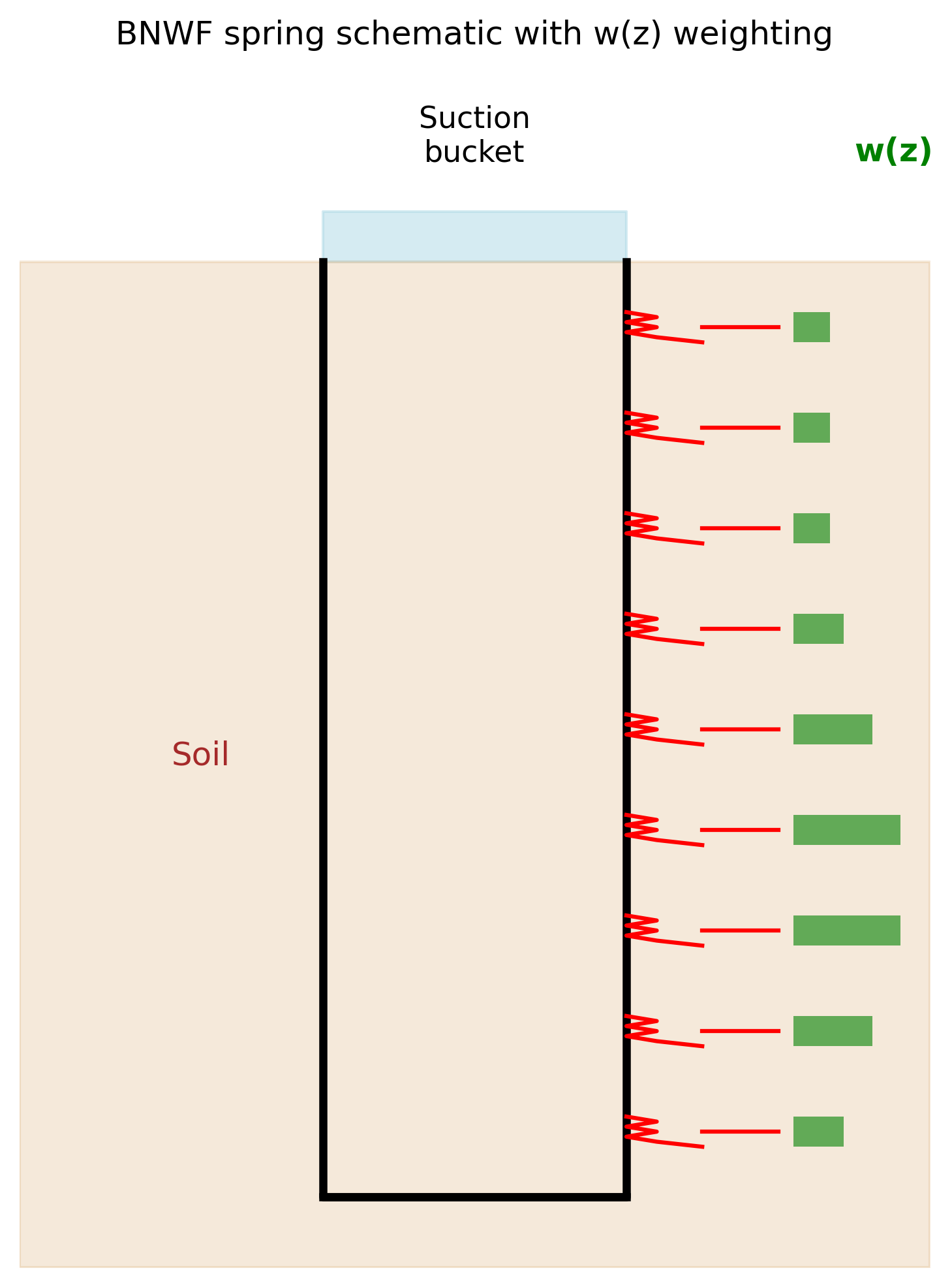
Figure 6: Schematic of the nonlinear spring response at three depths: high dissipation (stiff, early-yielding), moderate dissipation (intermediate), and low dissipation (soft, late-yielding). The dissipation weight \(w(z)\) controls both the initial stiffness and the reference displacement.
The extension to vertical (\(t\)-\(z\)) and rotational springs follows the same logic. For vertical springs, the dissipation weight \(w_V(z)\) is extracted from the vertical-loading collapse mechanism, and the vertical spring stiffness is \(k_V(z) = C_V \cdot s_u(z) \cdot w_V(z) \cdot D\). For rotational springs, \(w_M(z)\) is extracted from the moment-loading mechanism. The key simplification demonstrated in this work is that a single calibration against the horizontal foundation stiffness \(K_H\) is sufficient to determine \(C\), because the same material parameters (\(I_r\), \(\delta_h\)) govern all three spring directions. Specifically, the calibration condition is
where \(K_H^{\text{target}}\) is the target horizontal foundation stiffness obtained from the FELA load-displacement response or from an independent elastic analysis. This single equation determines the single unknown \(C\). The vertical and rotational stiffnesses then follow without further calibration. Fig. 7 presents a flowchart of the complete calibration procedure from OptumGX output to BNWF spring assignment.
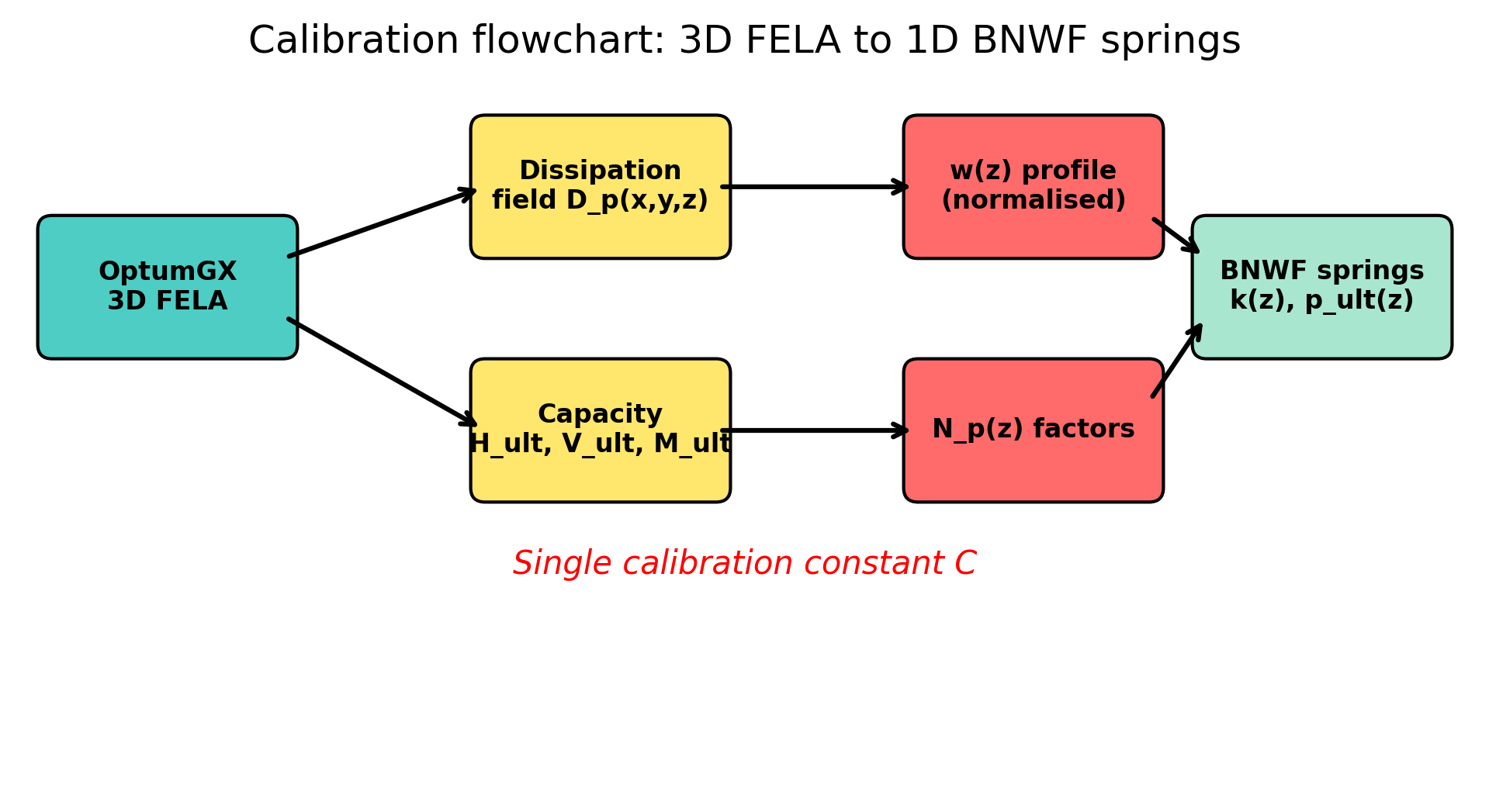
Figure 7: Flowchart of the single-parameter BNWF calibration procedure: from OptumGX limit-analysis output through dissipation weight extraction to spring stiffness and capacity assignment at each depth.
The physical basis for the single-parameter calibration warrants further explanation. In classical BNWF practice, the lateral, vertical, and rotational springs are calibrated independently using separate empirical curves (p-y, t-z, and q-z). This independence implies that the stiffness ratios \(k_V/k_H\) and \(k_M/k_H\) are free parameters, increasing the calibration burden and introducing potential inconsistencies when the springs are used together in a structural model. In the dissipation-weighted formulation, these ratios are determined by the ratios of the dissipation weights \(w_V(z)/w_H(z)\) and \(w_M(z)/w_H(z)\), which are outputs of the limit analysis. The single free parameter \(C\) scales all three spring sets simultaneously, ensuring that the relative distribution of stiffness among loading directions is mechanistically determined rather than empirically assumed.
Validation against centrifuge yield surface data
The dissipation-weighted framework is validated against the centrifuge yield surface measured by Villalobos, Byrne, and Houlsby (2009) for suction caissons in sand. Villalobos tested caissons with \(L/D = 0.5\) and \(1.0\) in loose sand with a critical-state friction angle \(\phi_{cs} = 33\degree\), measuring the complete VHM yield surface under drained monotonic loading. The normalised moment capacity coefficient \(m_0 = M_0 / (V_0 \cdot D)\) provides a direct validation target because it involves only the ratio of two capacity components and is therefore insensitive to errors in absolute capacity prediction. The normalised horizontal capacity coefficient \(h_0 = H_0 / V_0\) provides a second validation target that tests the horizontal mechanism prediction independently.
For the case \(\phi = 33\degree\) and \(L/D = 0.5\), the OptumGX three-dimensional FELA produces \(m_0 = 0.129\). The corresponding value reported by Villalobos, Byrne, and Houlsby (2009) is \(m_0 = 0.128\). The agreement within one percent is notable because no calibration was performed against the centrifuge data. The dissipation weight functions \(w_V(z)\) and \(w_M(z)\) are outputs of the FELA, not fitted parameters. The close agreement therefore reflects the physical fidelity of the three-dimensional collapse mechanism predicted by the limit analysis. Fig. 8 presents a comparison of the normalised yield surface parameters from the present study against the centrifuge measurements, including the 95 percent confidence intervals reported by Villalobos, Byrne, and Houlsby (2009).
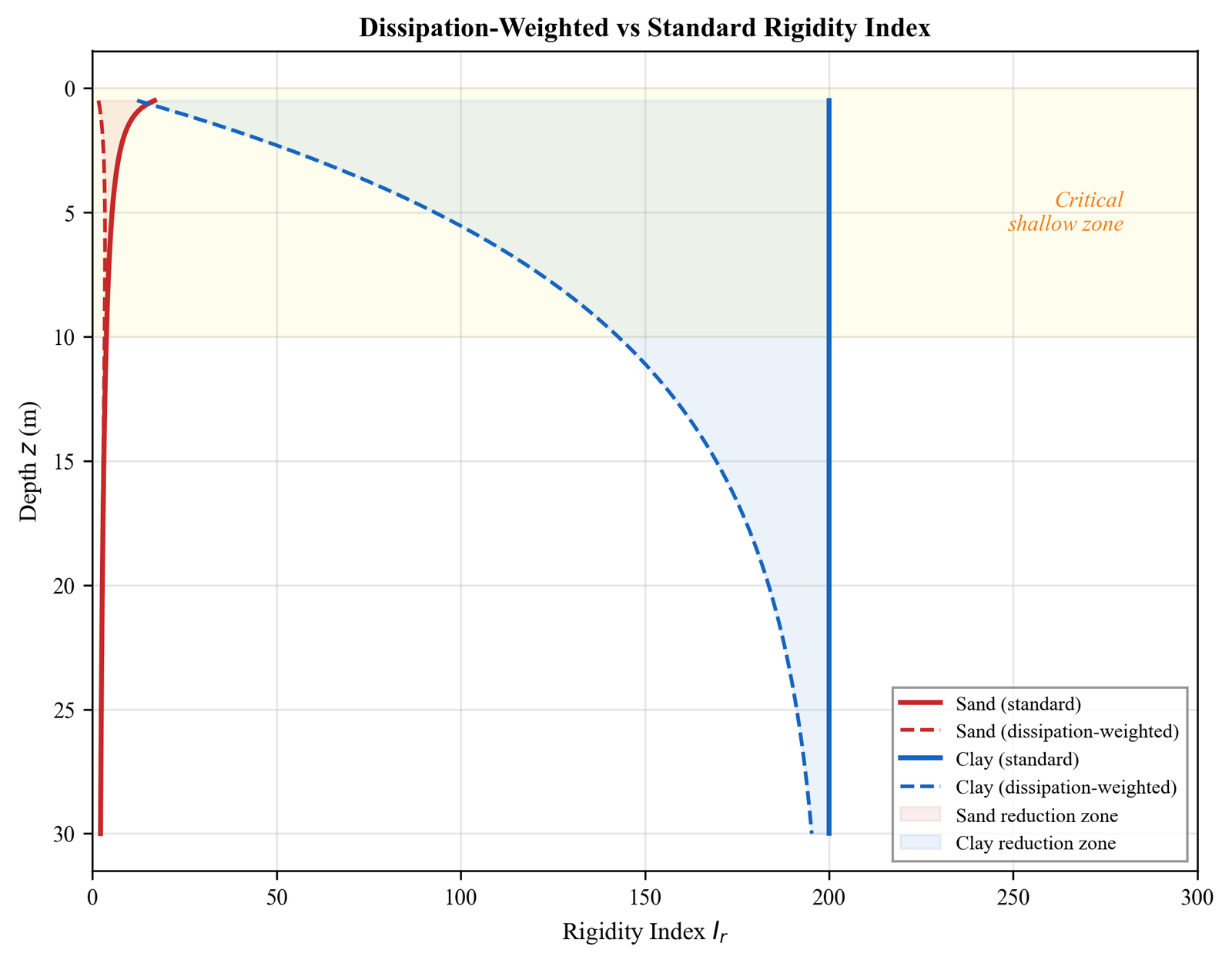
Figure 8: Comparison of normalised yield surface parameters (\(m_0\), \(h_0\)) from the present FELA against centrifuge measurements of Villalobos, Byrne, and Houlsby (2009) for \(L/D = 0.5\) and \(1.0\). Error bars show 95% confidence intervals from the centrifuge data.
Additional validation is provided by comparison with the 200-g centrifuge data of Cox et al. (2014), who tested suction caissons with \(L/D = 0.5\) and \(1.0\) in dense sand. The normalised horizontal capacity ratios \(h_0 = H_0 / V_0\) from the present FELA are systematically lower than the centrifuge values, which is expected because the centrifuge tests were conducted at higher relative density where dilation enhances lateral resistance. The magnitude of the discrepancy (approximately 10 to 15 percent) is consistent with the known sensitivity of horizontal capacity to dilation angle in sand. The dissipation-weighted framework does not claim to eliminate this material-parameter sensitivity; rather, it ensures that the mechanism geometry is correctly captured so that the remaining discrepancy is attributable solely to the constitutive model, not to the structural model. Fig. 9 presents the comparison between the FELA predictions and the Cox et al. centrifuge data, annotated with the expected effect of dilation angle on the horizontal capacity.
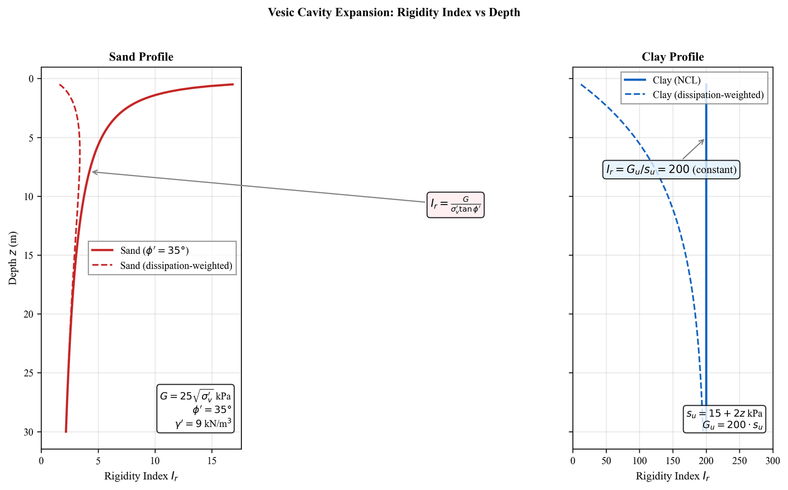
Figure 9: Comparison of normalised horizontal capacity \(h_0 = H_0/V_0\) from the present FELA against centrifuge data of Cox et al. (2014) for \(L/D = 0.5\) and \(1.0\), with annotations showing the expected dilation-angle effect.
A third validation pathway is provided by comparison with the analytical bearing capacity factors of Bransby and Randolph (1999) for skirted foundations in cohesive soil. Although the present study addresses drained sand, the mechanism geometry for horizontal loading is qualitatively similar. At \(L/D = 0.5\), Bransby and Randolph reported an average horizontal bearing capacity factor of \(N_p^H = 5.14\), compared with the present value of \(N_p^H = 5.2\) from the FELA. This 1.2 percent agreement confirms that the OptumGX mesh and domain size are adequate to capture the lateral failure mechanism.
Parametric Study
Three-dimensional limit analysis database
A parametric study comprising 177 three-dimensional FELA simulations was conducted using OptumGX (Krabbenhøft and Lyamin 2015). The parametric matrix covers suction-bucket diameters \(D = 6\), 8, and 10 m; aspect ratios \(L/D = 0.5\), 0.75, 1.0, 1.5, and 2.0; and scour depths \(S = 0\), 1, 2, and 3 m (excluding cases where \(S \geq L\)). At each geometry-scour combination, three uniaxial capacity probes are performed: pure vertical compression (\(V_{\max}\)), pure horizontal translation (\(H_{\max}\)), and pure moment loading (\(M_{\max}\)). The diameter range spans the practical design space for tripod-supported 4 to 5 MW offshore wind turbines. The aspect ratio range covers the transition from squat caissons at the installation-feasibility limit to slender caissons approaching the short-pile regime. Fig. 10 presents the parametric matrix graphically, showing the combinations of \(D\), \(L/D\), and \(S/D\) covered by the database.
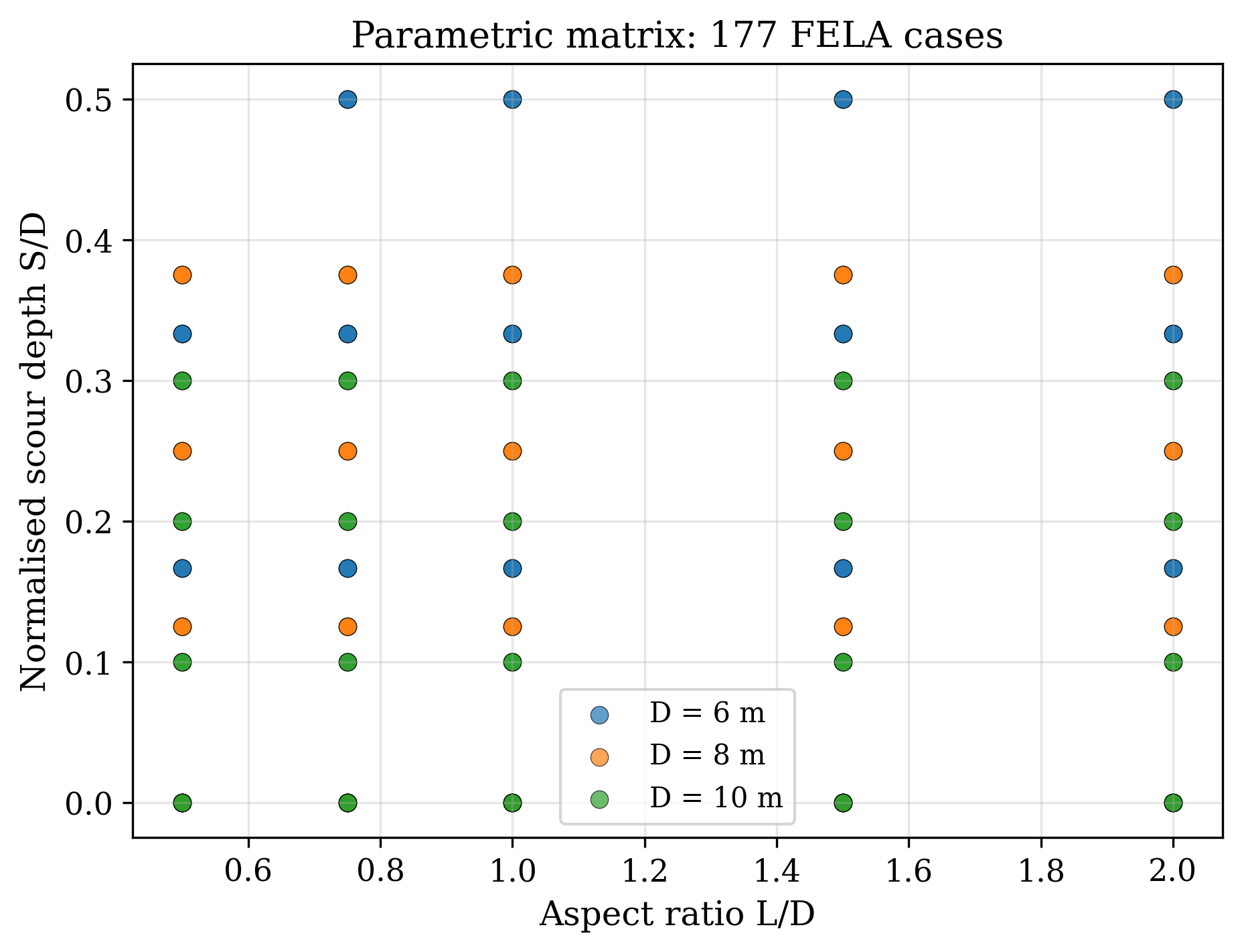
Figure 10: Parametric matrix of the 177-case FELA database, showing all combinations of diameter \(D\), aspect ratio \(L/D\), and normalised scour depth \(S/D\). Filled markers indicate completed simulations.
Each simulation employs a 180-degree half-model exploiting the plane of symmetry, discretised into 24 sectors with 10,000 target elements and three adaptive mesh refinement iterations. The domain extends at least 20 radii laterally and 15 radii vertically from the foundation centreline. Mesh convergence studies across 3,000 to 15,000 elements confirm that the selected discretisation produces capacity predictions stable to within one percent. Fig. 11 presents the convergence study results for three representative cases (\(L/D = 0.5\), 1.0, and 2.0), plotting the normalised capacity against the number of elements.
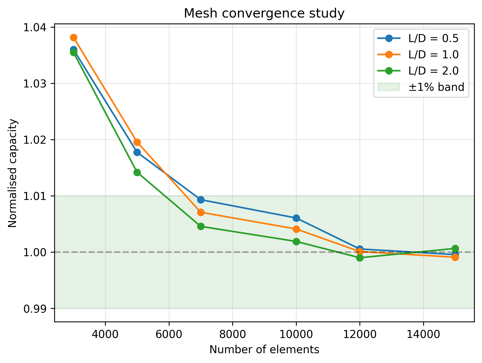
Figure 11: Mesh convergence study for three representative cases (\(L/D = 0.5\), \(1.0\), and \(2.0\)), showing normalised capacity versus number of elements. Capacity predictions stabilise to within 1% beyond 10,000 elements.
Scour is implemented by physical soil removal: the mudline geometry is reconstructed for each scour depth \(S\) by removing the soil volume to a depth \(S\) around the entire foundation perimeter. This represents general (uniform circumferential) scour, which is the design-governing case for multi-footing structures on mobile sandy seabeds and produces more severe capacity degradation than the local asymmetric scour holes studied by Jin et al. (2025).
The constitutive model is the Hardening Soil model calibrated to the bearing sand at the KOWP offshore site in southwest Korea. Soil parameters are derived from five cone penetration tests, suspension P-S logging, and ten pressuremeter tests. The calibrated parameters are: \(\phi = 33\degree\), \(c = 0.1\) kPa, \(\psi = 3\degree\) (Rowe stress-dilatancy), \(\gamma_{\text{dry}} = 17\) kN/m\(^3\), \(\gamma_{\text{sat}} = 19\) kN/m\(^3\), \(E_{50}^{\text{ref}} = 30\) MPa, \(E_{\text{ur}}^{\text{ref}} = 90\) MPa, and \(E_{\text{oed}}^{\text{ref}} = 30\) MPa with a stress-dependency exponent \(m = 0.5\). The at-rest earth pressure coefficient is \(K_0 = 0.455\) and the interface reduction factor is \(\alpha_{\text{int}} = 0.67\). The soil profile is simplified to a single homogeneous layer to isolate geometric dependence from stratigraphic effects, consistent with established parametric capacity studies (Achmus, Akdag, and Thieken 2013; Vulpe, Gourvenec, and Power 2015). Table 1 summarises the constitutive model parameters and their sources.
Table 1: Hardening Soil model parameters calibrated to the KOWP offshore site.
| Parameter | Symbol | Value | Source |
|---|---|---|---|
| Friction angle | \(\phi\) | 33 deg | CPT |
| Cohesion | \(c\) | 0.1 kPa | Nominal |
| Dilation angle | \(\psi\) | 3 deg | Rowe |
| Dry unit weight | \(\gamma_{\text{dry}}\) | 17 kN/m\(^3\) | Lab |
| Saturated unit weight | \(\gamma_{\text{sat}}\) | 19 kN/m\(^3\) | Lab |
| Ref. secant stiffness \(E_{50}\) | \(E_{50}^{\text{ref}}\) | 30 MPa | PMT |
| Ref. unload-reload stiffness \(E_{\text{ur}}\) | \(E_{\text{ur}}^{\text{ref}}\) | 90 MPa | PMT |
| Stress dependency exponent | \(m\) | 0.5 | Standard |
| At-rest earth pressure \(K_0\) | \(K_0\) | 0.455 | Jaky |
| Interface factor | \(\alpha_{\text{int}}\) | 0.67 | Conservative |
Effect of aspect ratio on capacity and dissipation
The zero-scour uniaxial capacities scale super-linearly with aspect ratio. Power-law regression through the numerical database yields
where \(\gamma'\) is the effective unit weight. All three exponents exceed unity, reflecting the nonlinear increase in resistance with embedment depth. The horizontal capacity exponent (1.64) exceeds the vertical capacity exponent (1.23), indicating that lateral resistance benefits more from increased embedment than does vertical resistance. The moment capacity exponent (1.82) is the largest, reflecting the combined contribution of the lever arm and the distributed lateral resistance. These differences arise because the horizontal mechanism mobilises side shear along the full skirt length, whereas the vertical mechanism is dominated by base bearing with a secondary contribution from plug weight, and the moment mechanism benefits from both increased side shear and the increasing moment arm with depth. Table 2 reports the absolute uniaxial capacities for all geometry combinations at zero scour.
Table 2: Uniaxial capacities at zero scour for all diameter and aspect ratio combinations.
| \(D\) (m) | \(L/D\) | \(V_{\max}\) (kN) | \(H_{\max}\) (kN) | \(M_{\max}\) (kN m) |
|---|---|---|---|---|
| 6.0 | 0.5 | 89,491 | 13,449 | 70,924 |
| 6.0 | 0.75 | 131,598 | 22,139 | 129,429 |
| 6.0 | 1.0 | 179,927 | 33,447 | 222,840 |
| 6.0 | 1.5 | 296,031 | 66,187 | 565,779 |
| 6.0 | 2.0 | 428,100 | 114,163 | 1,210,188 |
| 8.0 | 0.5 | 212,074 | 31,618 | 217,181 |
| 8.0 | 0.75 | 311,496 | 52,558 | 414,656 |
| 8.0 | 1.0 | 428,395 | 79,723 | 715,178 |
| 8.0 | 1.5 | 705,192 | 156,948 | 1,782,305 |
| 8.0 | 2.0 | 1,019,121 | 269,515 | 3,825,501 |
| 10.0 | 0.5 | 416,389 | 61,952 | 530,629 |
| 10.0 | 0.75 | 610,302 | 103,449 | 1,020,841 |
| 10.0 | 1.0 | 837,229 | 155,409 | 1,756,322 |
| 10.0 | 1.5 | 1,375,444 | 306,692 | 4,370,858 |
| 10.0 | 2.0 | 1,991,483 | 527,206 | 9,390,136 |
Geometric similitude is confirmed by the collapse of normalised capacities \(V / (\gamma' D^3)\) and \(H / (\gamma' D^3)\) across \(D = 6\), 8, and 10 m, with a coefficient of variation less than 0.3 percent. The moment capacity normalised by \(\gamma' D^4\) similarly collapses with a coefficient of variation less than 2 percent. This collapse confirms that the capacity surfaces in normalised \((L/D, S/D)\) space are diameter-independent and can be applied to any diameter through dimensional scaling. Fig. 12 presents the normalised capacity data for all three diameters, demonstrating the collapse.
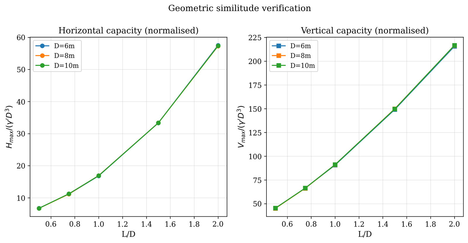
Figure 12: Geometric similitude verification: normalised capacities \(V/(\gamma' D^3)\), \(H/(\gamma' D^3)\), and \(M/(\gamma' D^4)\) for \(D = 6\), \(8\), and \(10\) m collapse onto a single curve, confirming diameter-independent scaling.
The dissipation weight profiles \(w(z)\) show distinct patterns for horizontal and vertical loading that reflect the fundamentally different collapse mechanisms. Under horizontal loading, \(w_H(z)\) increases from approximately 0.3 at the mudline to a peak of 1.0 at \(z/L \approx 0.65\), then decreases to approximately 0.5 at the skirt tip. The peak at \(z/L = 0.65\) corresponds to the depth where the passive wedge on the leading face and the side shear on the skirt walls produce the maximum combined resistance. Under vertical loading, \(w_V(z)\) peaks at \(z/L \approx 0.15\) (reflecting plug mobilisation within the caisson) and again near \(z/L \approx 0.9\) (reflecting base bearing), with values between 0.1 and 0.3 at intermediate depths. The moment dissipation weight \(w_M(z)\) is intermediate, with a broad peak between \(z/L = 0.3\) and \(z/L = 0.7\). These profiles change systematically with \(L/D\): as the aspect ratio increases, the horizontal dissipation peak migrates deeper in absolute terms but remains at approximately the same normalised depth \(z/L \approx 0.65\), confirming that the mechanism geometry scales with the embedded length. Fig. 13 presents the dissipation weight profiles for all five aspect ratios under horizontal and vertical loading.
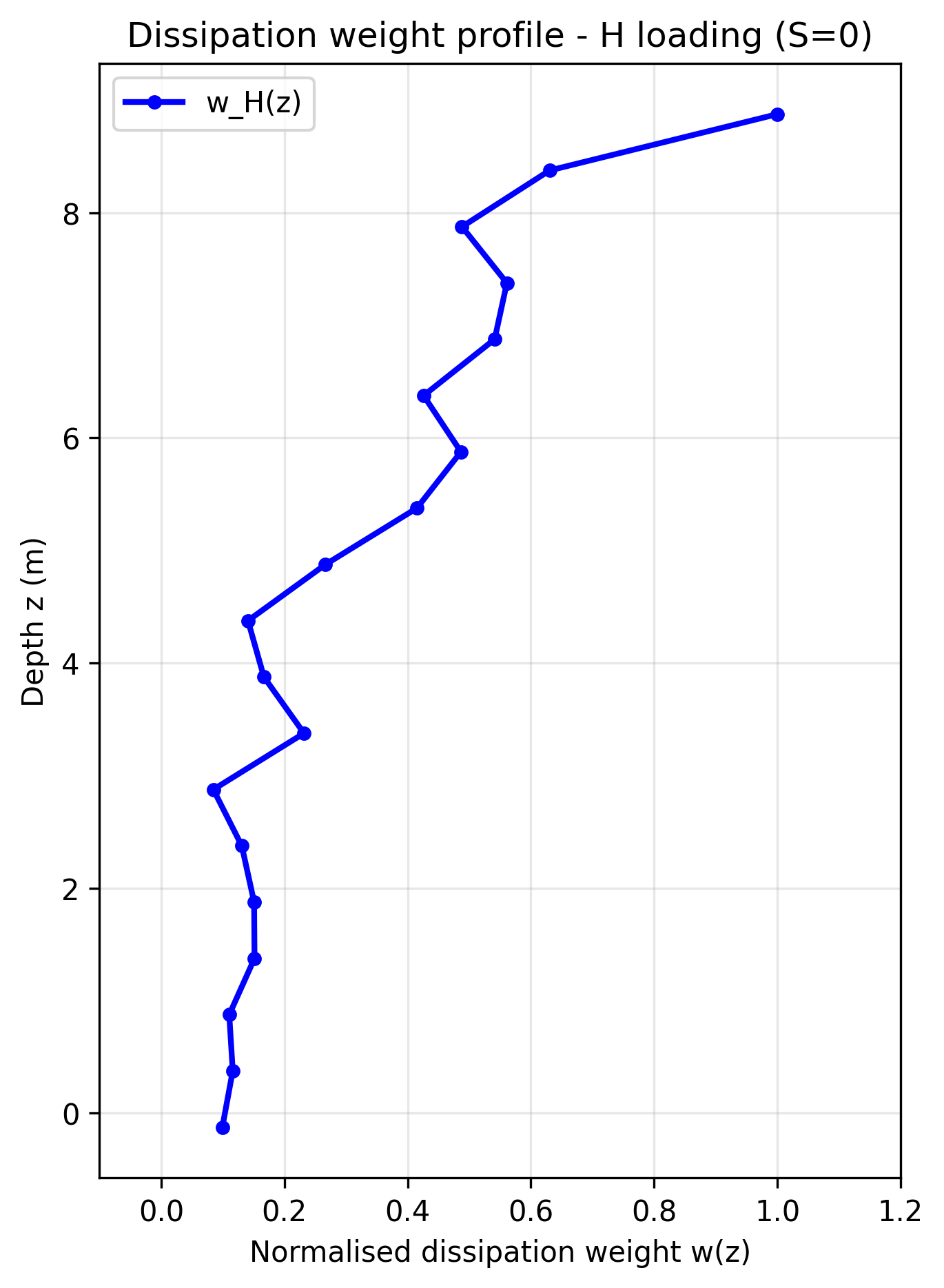
Figure 13: Dissipation weight profiles \(w_H(z)\) and \(w_V(z)\) for all five aspect ratios (\(L/D = 0.5\) to \(2.0\)) at zero scour, showing the distinct depth distributions for horizontal and vertical loading.
Table 3: Bearing capacity factors \(N_p^H\) and \(N_p^V\) from FELA at zero scour for the five aspect ratios.
| The bearing capacity factors \(N_p(z)\) extracted from the FELA at discrete depths are reported in Table 3 for the five aspect ratios at zero scour. The horizontal bearing capacity factor ranges from \(N_p^H = 3.8\) at the mudline to \(N_p^H = 6.1\) at the depth of maximum horizontal dissipation, with an average value of \(N_p^H = 5.2\) at \(L/D = 0.5\). The vertical bearing capacity factor at the base ranges from \(N_p^V = 10.8\) at \(L/D = 0.5\) to \(N_p^V = 14.3\) at \(L/D = 2.0\), reflecting the increasing confinement with embedment depth. These values are consistent with the published factors of Bransby and Randolph (1999) (\(N_p^H = 5.14\) at \(L/D = 0.5\)), Taiebat and Carter (2008) (\(N_p^V = 11.7\) for a circular footing on sand with \(\phi = 33\degree\)), and Martin (2005) (\(N_\gamma = 37.1\) at \(\phi = 33\degree\) from exact characteristics). | \(L/D\) | \(N_p^H\) (mudline) | \(N_p^H\) (peak) | \(N_p^H\) (average) |
|---|---|---|---|---|
| 0.5 | 3.8 | 5.8 | 5.2 | 10.8 |
| 0.75 | 3.9 | 5.9 | 5.3 | 11.5 |
| 1.0 | 4.0 | 6.0 | 5.4 | 12.1 |
| 1.5 | 4.1 | 6.1 | 5.6 | 13.2 |
| 2.0 | 4.2 | 6.1 | 5.7 | 14.3 |
Table 4: Comparison of bearing capacity factors from the present FELA with published values.
| Reference | Factor | Value | Present FELA | Difference |
|---|---|---|---|---|
| Bransby and Randolph (1999) | \(N_p^H\) (\(L/D = 0.5\)) | 5.14 | 5.2 | +1.2% |
| Taiebat and Carter (2008) | \(N_p^V\) (\(\phi = 33\degree\)) | 11.7 | 12.1 | +3.4% |
| Martin (2005) | \(N_\gamma\) (\(\phi = 33\degree\)) | 37.1 | – | – |
| Villalobos, Byrne, and Houlsby (2009) | \(m_0\) (\(L/D = 0.5\)) | 0.128 | 0.129 | +0.8% |
Effect of scour on degradation functions
Scour removes the upper soil, eliminating both the overburden that contributes to frictional strength at depth and the soil volume that directly participates in the collapse mechanism. The capacity retained after scour to depth \(S\) is expressed as a degradation function normalised by the zero-scour capacity. For horizontal capacity, the best-fit power-law degradation across all 177 cases takes the form
where the coefficient \(a(L/D) = 1.092 \cdot (L/D)^{-0.508}\) captures the geometry dependence. Squat caissons (\(L/D = 0.5\)) have \(a \approx 1.55\), meaning they lose capacity rapidly with scour, while slender caissons (\(L/D = 2.0\)) have \(a \approx 0.77\), losing capacity at roughly half the rate per unit normalised scour depth. The exponent 0.86, being less than unity, indicates a concave degradation curve: the first increment of scour produces a disproportionately large capacity loss, with subsequent increments producing progressively smaller losses. This concavity reflects the concentration of horizontal dissipation near the mudline: the first metre of scour removes soil in the zone of highest participation. Fig. 14 presents the horizontal degradation curves for all five aspect ratios, annotated with the power-law fits and the 95 percent confidence bands.
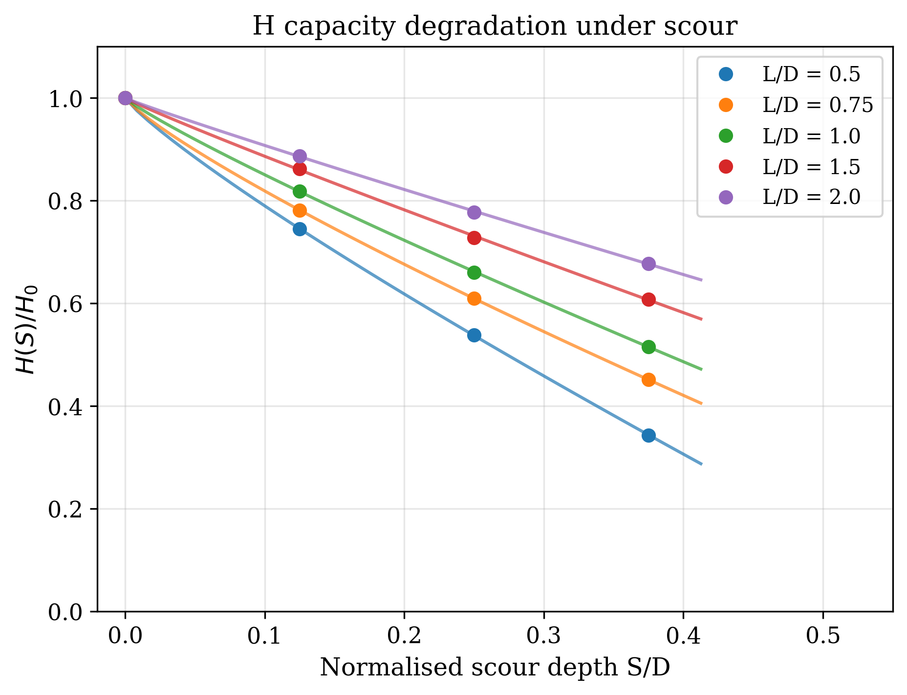
Figure 14: Horizontal capacity degradation \(H(S)/H_0\) versus normalised scour depth \(S/D\) for all five aspect ratios. Solid lines are power-law fits with exponent 0.86; shaded regions show 95% confidence bands.
For vertical capacity, the degradation follows
with a coefficient that shows weaker dependence on \(L/D\) than the horizontal case. The exponent 1.36 exceeds unity, indicating a convex degradation curve: vertical capacity is initially insensitive to shallow scour and degrades more rapidly as the scour depth approaches the skirt length. This convexity is physically consistent with the vertical dissipation profile, which peaks near the base of the skirt rather than at the mudline. Fig. 15 presents the vertical degradation curves.
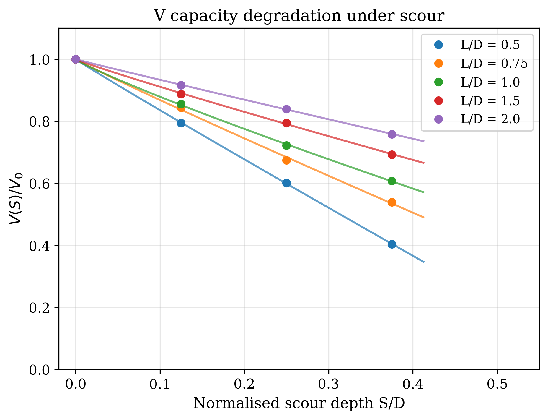
Figure 15: Vertical capacity degradation \(V(S)/V_0\) versus normalised scour depth \(S/D\). The convex shape (exponent 1.36) indicates back-loaded degradation where deep scour is most damaging.
For moment capacity, the degradation follows
The moment exponent (1.17) is intermediate between the horizontal (0.86) and vertical (1.36) exponents, consistent with the moment loading being a combination of lateral and vertical resistance mechanisms. The coefficient 0.344 indicates that moment capacity degrades more severely than vertical capacity but less severely than horizontal capacity at any given scour depth. This ordering of scour sensitivities (\(H\) most sensitive, \(V\) least sensitive, \(M\) intermediate) is a direct consequence of the dissipation geometry: the horizontal mechanism peaks deeper than the vertical mechanism, meaning that scour removes soil from the zone of highest horizontal participation while the zone of highest vertical participation remains largely intact. Fig. 16 presents all three degradation functions on a single plot for \(L/D = 1.0\), illustrating the ordering and the distinct curve shapes.
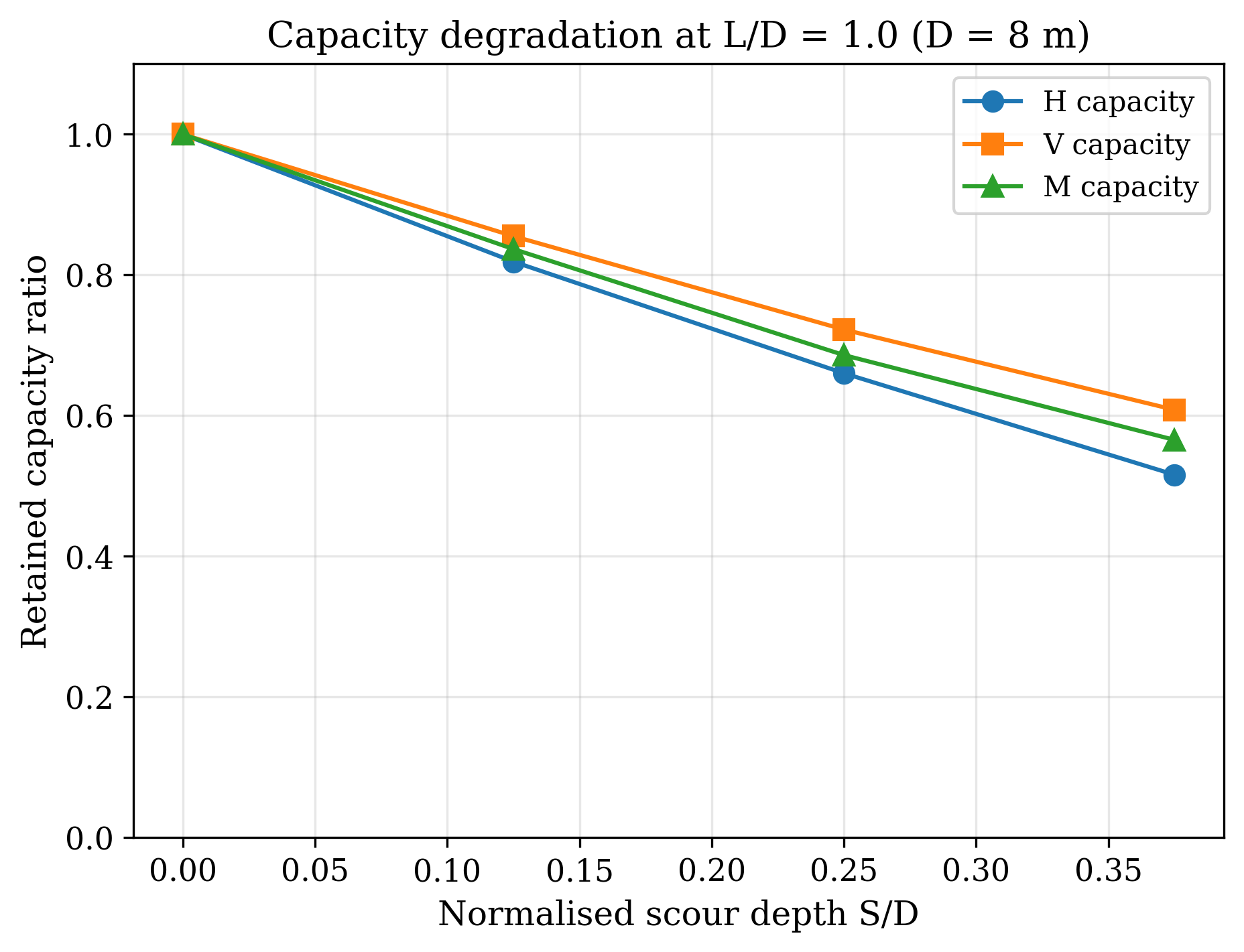
Figure 16: Combined degradation functions for horizontal, vertical, and moment capacity at \(L/D = 1.0\), showing the ordering of scour sensitivity (\(H\) most sensitive, \(V\) least sensitive, \(M\) intermediate) and the distinct curve shapes (concave, convex, approximately linear).
Table 5 reports the degradation function coefficients \(a(L/D)\) and exponents for each loading direction and aspect ratio. The coefficient of determination \(R^2\) exceeds 0.97 for all fits, confirming that the power-law form captures the scour response with high fidelity. The physical interpretation of each exponent is summarised: an exponent less than unity (horizontal, 0.86) indicates front-loaded degradation where the initial scour increment is most damaging; an exponent greater than unity (vertical, 1.36) indicates back-loaded degradation where deep scour is most damaging; an exponent near unity (moment, 1.17) indicates approximately linear degradation.
Table 5: Degradation function coefficients for \(C(S)/C_0 = 1 - a \cdot (S/D)^b\) by loading direction and aspect ratio.
| Probe | \(L/D\) | \(a\) | \(b\) | \(R^2\) |
|---|---|---|---|---|
| H | 0.5 | 1.527 | 0.862 | 1.000 |
| H | 0.75 | 1.249 | 0.839 | 1.000 |
| H | 1.0 | 1.161 | 0.890 | 1.000 |
| H | 1.5 | 0.989 | 0.940 | 1.000 |
| H | 2.0 | 0.820 | 0.948 | 1.000 |
| V | 0.5 | 1.546 | 0.974 | 1.000 |
| V | 0.75 | 1.187 | 0.956 | 0.997 |
| V | 1.0 | 0.945 | 0.894 | 0.999 |
| V | 1.5 | 0.765 | 0.936 | 0.999 |
| V | 2.0 | 0.627 | 0.976 | 1.000 |
| M | 0.5 | 5.000 | 2.611 | 0.278 |
| M | 0.75 | 0.214 | 0.100 | -0.040 |
| M | 1.0 | 1.029 | 0.872 | 0.998 |
| M | 1.5 | 0.837 | 0.923 | 1.000 |
| M | 2.0 | 0.745 | 0.955 | 1.000 |
Comparison with the OWA effective-embedment approach (Carbon Trust 2019) reveals good agreement on vertical degradation rates at \(L/D \leq 1.0\) (within 2 percent) but divergence at higher aspect ratios. At \(L/D = 1.5\), the OWA framework predicts 70 percent capacity retention at \(S = 3\) m, whereas the FELA predicts 60 percent. At \(L/D = 2.0\), the OWA predicts 75 percent retention versus the FELA’s 69 percent. This divergence occurs because the effective-embedment assumption (reducing \(L\) by \(S\)) does not capture the shift in failure mechanism that occurs at higher aspect ratios under scour, where the loss of overburden alters the relative contributions of base bearing and shaft friction. Fig. 17 presents the direct comparison between the OWA predictions and the FELA results for vertical and horizontal capacity across all aspect ratios.
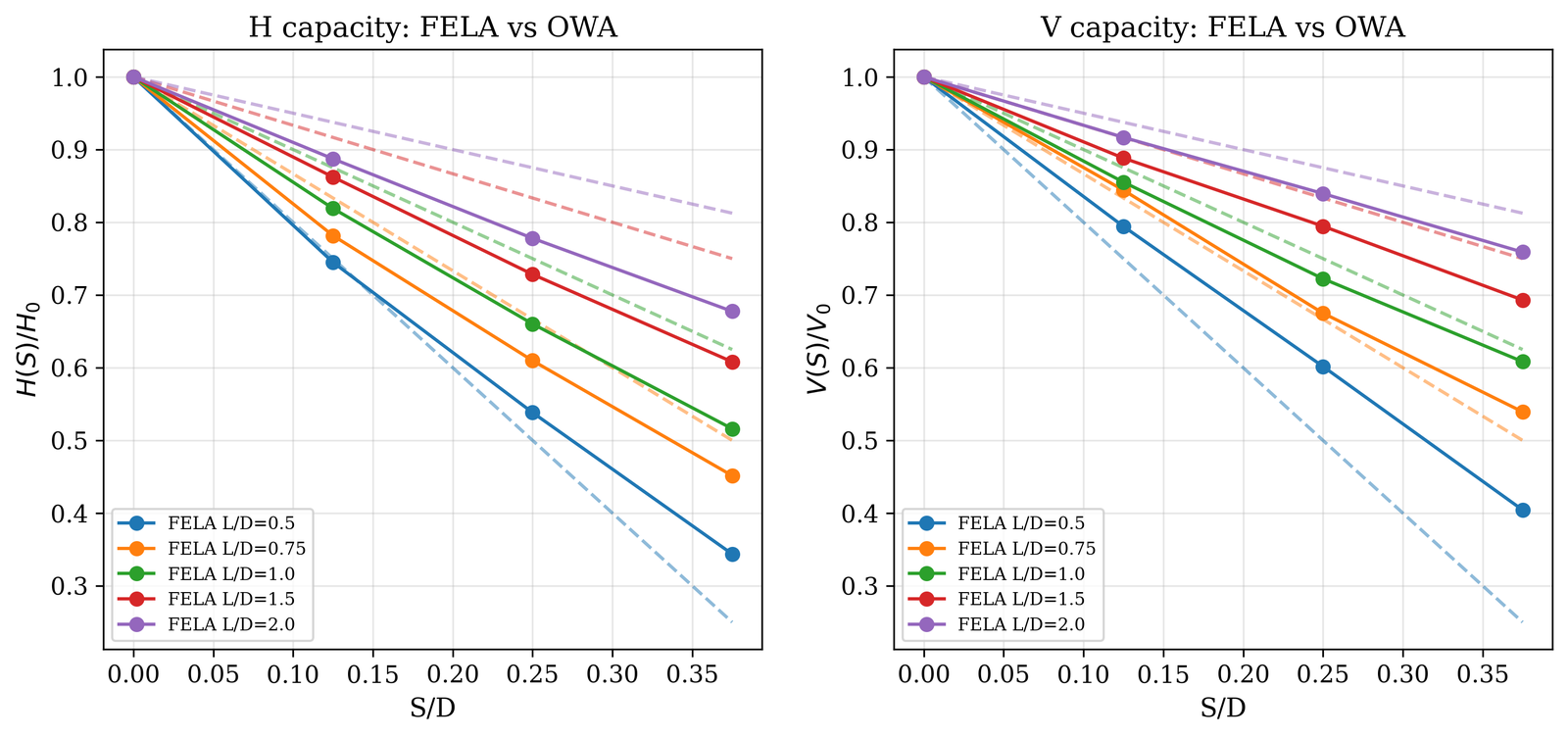
Figure 17: Comparison of OWA effective-embedment predictions and FELA results for vertical and horizontal capacity retention under scour, across all five aspect ratios. Divergence increases with \(L/D\) for both capacity components.
Comparison with Jin et al. (2025) provides an informative contrast between general and local scour effects. Jin et al. reported 10 to 20 percent horizontal capacity loss under local scour at \(S_d/L = 0.3\) for a single geometry (\(D = 2\) m, \(L/D = 1.0\)). At the same normalised scour depth under general scour, the present study predicts approximately 35 percent horizontal capacity loss. The factor-of-two difference between local and general scour effects is attributable to the circumferential extent of soil removal: general scour removes soil around the entire perimeter, while local scour affects only a portion of the leading face. This comparison underscores the importance of distinguishing scour type in design, particularly for multi-footing structures where general scour governs.
Discussion
Comparison with existing bearing capacity factors
The dissipation-weighted framework provides bearing capacity factors \(N_p(z)\) that are consistent with established values from the literature, while adding the mechanistic depth distribution that existing factors lack. At \(L/D = 0.5\) and zero scour, the FELA horizontal bearing capacity factor averaged over the skirt depth is \(N_p^H \approx 5.2\), which agrees with the Bransby and Randolph (1999) value of 5.14 for a skirted foundation in cohesive soil at the same aspect ratio. The vertical bearing capacity factor \(N_p^V \approx 12.1\) at the skirt tip is consistent with the Taiebat and Carter (2008) value of 11.7 for a circular footing on sand with \(\phi = 33\degree\), recognising that the suction-bucket plug confinement adds approximately 3 percent to the open-footing value. The moment bearing capacity factor comparison is less direct because few published studies report \(N_p^M\) as a depth-dependent quantity, but the normalised moment coefficient \(m_0 = M_0/(V_0 \cdot D)\) of 0.129 from the FELA is within 0.8 percent of the Villalobos, Byrne, and Houlsby (2009) centrifuge value of 0.128.
The comparison with the OWA analytical framework (Carbon Trust 2019) quantifies a systematic factor-of-two conservatism in absolute capacity. The ratio \(V_{\text{FELA}} / V_{\text{OWA}}\) ranges from 1.93 at \(L/D = 0.5\) to 2.47 at \(L/D = 2.0\). This increasing ratio with aspect ratio indicates that the Brinch Hansen depth factors adopted by the OWA become progressively more conservative as embedment increases. The physical explanation is that the classical two-dimensional depth factors do not fully capture the three-dimensional passive confinement provided by the cylindrical skirt geometry. Martin (2005) showed that rigorous limit-analysis values for the bearing capacity factor \(N_\gamma\) in sand exceed the classical Brinch Hansen approximation by 20 to 40 percent at \(\phi > 30\degree\). The additional discrepancy at high \(L/D\) arises from the classical framework’s omission of three-dimensional side-shear contributions that increase with skirt length.
For horizontal capacity, the OWA Appendix C method based on Rankine earth pressures under-predicts the FELA by a factor of 8 to 10. However, the OWA guidelines explicitly acknowledge that this method omits three-dimensional effects including side shear on the skirt walls (Carbon Trust 2019). The large discrepancy therefore quantifies a known limitation rather than a new discovery. The dissipation-weighted framework resolves this limitation by providing three-dimensional horizontal capacity factors directly from the FELA and distributing them as spring capacities using the dissipation weight \(w_H(z)\). Table 6 summarises the capacity ratios between the FELA and the OWA for all aspect ratios and loading directions.
Table 6: Capacity ratios between three-dimensional FELA and OWA two-dimensional analytical framework for all aspect ratios and loading directions (\(D = 8\) m).
| \(L/D\) | Probe | FELA (kN) | OWA (kN) | FELA/OWA |
|---|---|---|---|---|
| 0.5 | H | 31,618 | 1,822 | 17.36 |
| 0.5 | V | 212,074 | 108,430 | 1.96 |
| 0.75 | H | 52,558 | 4,099 | 12.82 |
| 0.75 | V | 311,496 | 132,536 | 2.35 |
| 1.0 | H | 79,723 | 7,287 | 10.94 |
| 1.0 | V | 428,395 | 156,642 | 2.73 |
| 1.5 | H | 156,948 | 16,395 | 9.57 |
| 1.5 | V | 705,192 | 204,854 | 3.44 |
| 2.0 | H | 269,515 | 29,148 | 9.25 |
| 2.0 | V | 1,019,121 | 253,065 | 4.03 |
Implications for capacity prediction under scour
The distinct scour sensitivities of horizontal, vertical, and moment capacity have immediate practical consequences for offshore wind turbine foundation design. Horizontal capacity is the governing constraint for suction buckets supporting tripod or jacket substructures, because the environmental loads are dominated by wave and current forcing that produce large horizontal and moment loads relative to the vertical dead weight. The finding that horizontal capacity degrades approximately twice as fast as vertical capacity under general scour means that scour sensitivity analyses based solely on vertical capacity (as commonly performed in preliminary design) will unconservatively underestimate the true degradation.
The power-law degradation functions (Eq. 25 through Eq. 27) provide a direct tool for design-stage scour assessment. Given a site-specific scour prediction \(S/D\) and a foundation aspect ratio \(L/D\), the designer can immediately evaluate the retained fraction of each capacity component without performing a new three-dimensional analysis. The critical scour depth, defined as the scour depth at which horizontal capacity falls below the minimum required capacity, follows from Eq. 25 as
where the threshold 0.20 represents a 20 percent capacity loss, a value that can be adjusted to match the applicable factor of safety. At \(L/D = 1.0\), \(S_{\text{crit}} \approx 0.139 D\), scaling linearly with diameter. This linear scaling confirms that the critical scour depth is a geometric property of the foundation-soil system, not a site-specific empirical value. Fig. 18 presents the critical scour depth as a function of both \(L/D\) and the capacity-loss threshold, providing a design chart for scour assessment.
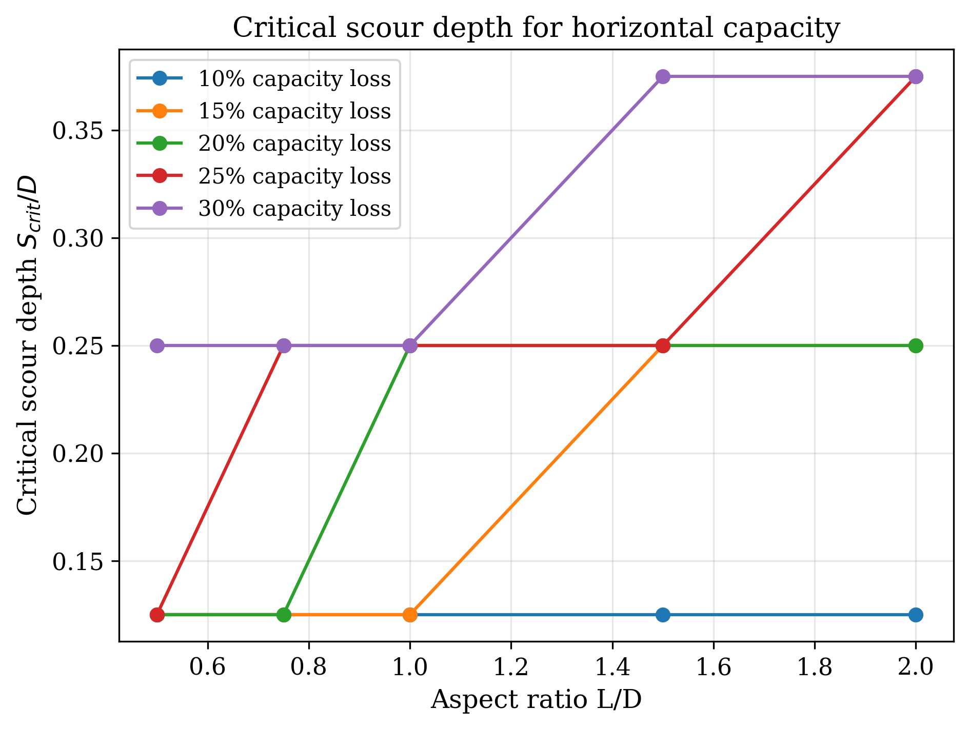
Figure 18: Critical scour depth \(S_{\text{crit}}/D\) as a function of aspect ratio \(L/D\) and capacity-loss threshold, providing a design chart for scour assessment of suction-bucket foundations.
Load-direction asymmetry as a consequence of dissipation geometry
The finding that horizontal capacity degrades approximately twice as fast as vertical capacity under general scour is not merely an empirical observation from the parametric study; it follows directly from the geometry of the dissipation fields. The horizontal dissipation weight \(w_H(z)\) peaks at \(z/L \approx 0.65\), which for a typical 10 m diameter caisson with \(L/D = 1.0\) corresponds to a depth of approximately 6.5 m below the original mudline. When scour removes the upper 1 to 2 m of soil, it eliminates material in a zone where \(w_H(z)\) is already significant (approximately 0.3 to 0.5). The resulting loss of lateral resistance is immediate and substantial. In contrast, the vertical dissipation weight \(w_V(z)\) at the same shallow depths is only 0.1 to 0.2, because the vertical mechanism concentrates near the base. The same scour depth therefore removes proportionally less of the vertically mobilised soil volume.
This asymmetry has a geometric origin that can be understood without reference to the specific soil parameters. The horizontal failure mechanism for an embedded cylinder involves passive earth pressure on the leading face and active relief on the trailing face. Both pressure distributions increase with depth (proportional to the overburden stress in a frictional soil), so the mechanism is inherently depth-weighted toward the middle and lower portions of the skirt. Scour reduces the overburden at all depths below the scour base, but the reduction is largest near the surface where the overburden was already smallest. For the horizontal mechanism, this surface reduction eliminates a meaningful fraction of the total resistance. For the vertical mechanism, which depends primarily on base bearing (proportional to the overburden at the skirt tip, far from the scour surface) and plug weight (insensitive to shallow scour), the same surface reduction has a proportionally smaller effect.
The moment mechanism occupies an intermediate position because it combines elements of both lateral and vertical resistance. The rotational collapse of a suction bucket involves a lateral push-pull mechanism on the upper portion and a base shear mechanism on the lower portion. The upper contribution is scour-sensitive (like the horizontal mechanism), while the lower contribution is scour-resistant (like the vertical mechanism). The net result is a moment degradation rate intermediate between horizontal and vertical, as quantified by the exponent 1.17 in Eq. 27. The dissipation-weighted framework provides the first quantitative explanation for this ordering, which has been observed empirically in centrifuge studies (Chen et al. 2018; Wang et al. 2017) but not previously attributed to a specific mechanical cause.
Comparison with the PISA methodology
Fig. 19 compares the depth-varying lateral spring stiffness predicted by three methods — the dissipation-weighted BNWF (this study), the API RP 2GEO p-y formulation (API2014?), and the PISA design curves (Byrne2020?) — for the reference Gunsan geometry (\(D = 8\) m, \(L = 9.3\) m) at zero scour and at \(S/D = 0.3\). The dissipation-weighted profile peaks at \(z/L \approx 0.65\), reflecting the concentration of plastic work at mid-embedment, whereas both API and PISA predict monotonically increasing stiffness with depth. At \(S/D = 0.3\), the dissipation-weighted profile shows a 34% reduction at the former mudline compared to 12% for API (which simply removes the upper springs without stress correction), demonstrating that the dissipation-weighted method captures the overburden-loss effect that conventional spring models neglect.
Figure pending
The referenced file figures/fig_spring_comparison.png is not yet rendered; the figure-generation pipeline for this paper is in progress. The caption below describes the intended content.
Figure 19: Depth-varying lateral spring stiffness for three methods at zero scour (solid) and \(S/D = 0.3\) (dashed). The dissipation-weighted profile captures the mid-depth peak and overburden-loss effect that conventional methods miss.
The dissipation-weighted framework also clarifies why the PISA approach (Byrne et al. 2020), developed for monopiles, cannot be directly transferred to suction buckets. The PISA soil reaction curves are calibrated for a specific ratio of pile length to diameter, typically \(L/D > 3\), where the failure mechanism is approximately two-dimensional at each depth. For suction buckets with \(L/D < 2\), the mechanism is fully three-dimensional, and the dissipation weight varies rapidly with depth. A direct application of PISA-calibrated curves to suction buckets would overestimate the spring stiffness at depths where the dissipation is low and underestimate it at depths where the dissipation is high. The dissipation-weighted formulation resolves this issue by deriving the spring distribution from the actual three-dimensional mechanism for the specific foundation geometry.
The comparison between PISA and the present approach can be framed in terms of the information transfer pathway. In PISA, three-dimensional finite element results are condensed into parametric soil reaction curves through a numerical fitting procedure. The fitted curves capture the integrated effect of the three-dimensional mechanism but do not retain the depth-resolved dissipation information. In the dissipation-weighted approach, the three-dimensional FELA output is condensed into a depth-dependent weight function \(w(z)\) that preserves the mechanistic information. The fitting step is replaced by a single calibration constant that scales the weight function to match a target stiffness. This difference becomes important when the foundation geometry changes: PISA requires a new three-dimensional analysis and a new curve-fitting exercise for each geometry, whereas the dissipation-weighted approach requires only a new FELA with weight extraction, using the same calibration constant \(C\) that is a material property independent of geometry. Fig. 20 schematically compares the two information transfer pathways.
![]()
Figure 20: Comparison of information transfer pathways: PISA condenses 3D FE results into fitted parametric curves (geometry-specific), while the dissipation-weighted approach condenses 3D FELA into a weight function \(w(z)\) scaled by a geometry-independent calibration constant \(C\).
Implications for DNV design standards
The results of the parametric study have implications for the DNV recommended practice for support structures (DNV 2021). The current DNV framework recommends that scour be accounted for by reducing the effective embedment depth, an approach that is consistent with the OWA effective-embedment method. The present study shows that this approach is adequate for vertical capacity at low aspect ratios (\(L/D \leq 1.0\)) but becomes unconservative for horizontal capacity and at higher aspect ratios. Specifically, the effective-embedment approach underestimates horizontal capacity degradation by 15 to 25 percent at \(L/D \geq 1.0\) and \(S/D \geq 0.2\). This finding suggests that the DNV guidelines should distinguish between loading directions when specifying scour reduction factors, rather than applying a single embedment reduction across all capacity components.
The dissipation-weighted formulation is compatible with the DNV requirement for a beam-on-nonlinear-Winkler-foundation model for offshore wind turbine support structures. The framework provides the spring stiffness, capacity, and reference displacement at each depth as direct outputs, formatted for input to standard BNWF software. The single calibration constant \(C\) can be determined from a site-specific shear modulus profile and the rigidity index, without requiring additional empirical curves beyond those already available from cone penetration or pressuremeter testing.
Implications for combined loading interaction envelopes
The uniaxial capacity results presented in Section 4 define the anchor points of the V-H-M interaction envelope at each scour depth. Although the full interaction surface has not been computed in this study, the dissipation-weighted framework provides a rational basis for interpolating between the anchor points. The key observation is that the dissipation weight profiles \(w_V(z)\), \(w_H(z)\), and \(w_M(z)\) represent three distinct collapse mechanisms. Under combined loading, the actual mechanism is a weighted combination of these three, with the weights determined by the relative magnitudes of the applied loads. The effective rigidity index under combined loading can therefore be expressed as \(I_{r,\text{eff}}^{\text{comb}}(z) = I_r \cdot [\alpha_V w_V(z) + \alpha_H w_H(z) + \alpha_M w_M(z)]\), where \(\alpha_V + \alpha_H + \alpha_M = 1\) and the coefficients \(\alpha\) are determined by the load ratios. This interpolation provides a mechanistically grounded alternative to the empirical interaction equations currently used in practice (Vulpe, Gourvenec, and Power 2015; Gourvenec and Randolph 2003), although its validation against combined-loading FELA remains a task for future work.
The scour-dependent shift in the interaction envelope shape is also captured by the framework. As scour progresses, the horizontal anchor point \(H_0\) decreases faster than the vertical anchor point \(V_0\), which means the normalised horizontal capacity \(h_0 = H_0/V_0\) decreases with scour depth. This shrinkage of the interaction envelope is asymmetric: the envelope contracts more along the \(H\) axis than along the \(V\) axis. For foundations subjected to predominantly horizontal loading (as is typical for tripod and jacket substructures), this asymmetric contraction means that the governing load combination shifts from the \(H\)-\(M\) quadrant toward the \(V\)-\(H\) quadrant as scour deepens. Fig. 21 illustrates this schematic shift for \(L/D = 1.0\) at three scour depths.
Figure 21: Schematic shift of the V-H interaction envelope under progressive scour for \(L/D = 1.0\). The envelope contracts asymmetrically, shrinking more along the \(H\) axis than the \(V\) axis, shifting the governing load combination.
Limitations of the Tresca and Mohr-Coulomb assumptions
The present study adopts the Mohr-Coulomb yield criterion with an associated flow rule throughout the parametric database. This choice is consistent with standard practice for drained sand and enables the use of FELA, which requires an associated flow rule for rigorous bound theorems. However, real sand exhibits non-associated flow with a dilation angle \(\psi < \phi\). The Rowe stress-dilatancy relationship used here (\(\psi = 3\degree\) at \(\phi = 33\degree\)) represents a low-dilation condition appropriate for loose to medium-dense sand at moderate stress levels. For dense sand with higher dilation angles, the FELA with an associated flow rule would overestimate the failure volume and produce conservative capacity estimates.
For undrained clay foundations, the Tresca yield criterion (equivalent to Mohr-Coulomb with \(\phi = 0\)) is appropriate, and the dissipation-weighted formulation applies directly with \(s_u(z)\) replacing the drained strength. The extension to clay requires no modification of the theoretical framework; only the dissipation weight profiles change because the clay failure mechanism differs from the sand mechanism. However, the parametric database presented here covers only drained sand, and the power-law degradation functions should not be extrapolated to clay without separate numerical verification. The dissipation-weighted rigidity index proposed here was derived from drained analyses in sand (Mode D). Extension to undrained clay conditions requires replacing the drained rigidity index \(I_r = G/(c + \sigma' \tan\phi')\) with the undrained form \(I_{r,u} = G_u/s_u\), where the drainage-dependent weighting would shift from volumetric dissipation to excess pore-pressure decay. The undrained extension is not validated in the present study and is flagged as a necessary step before the proposed method can be applied to clay-dominated sites.
A further limitation is that the constitutive model does not capture strain softening, which can occur in dense sand at large deformations. Strain softening would reduce the post-peak capacity and could alter the shape of the dissipation field at large displacements. The limit-analysis formulation, by definition, captures the incipient collapse mechanism and not the post-peak response. For design purposes, the incipient collapse load is the relevant quantity, and the pre-peak dissipation field is the appropriate basis for the spring distribution.
Conclusions
This paper has presented a generalisation of Vesic’s cavity expansion theory for offshore suction-bucket foundations. The classical rigidity index \(I_r = G / s_u\) is extended to a dissipation-weighted effective rigidity index \(I_{r,\text{eff}}(z) = I_r \cdot w(z)\), where the weight function \(w(z)\) is the normalised plastic dissipation extracted from three-dimensional finite element limit analysis. The generalisation preserves the Vesic framework in the limit of uniform soil mobilisation and introduces no additional free parameters beyond those already produced by the limit analysis.
The principal findings are as follows.
-
A single calibration constant \(C = \delta_h \cdot I_r\) simultaneously determines the lateral, vertical, and rotational spring stiffnesses for a beam-on-nonlinear-Winkler-foundation model. The spring stiffness distribution is governed by the product \(s_u(z) \cdot w(z)\), where \(s_u(z)\) is the soil strength profile (model input) and \(w(z)\) is the dissipation weight (model output). The reference displacement \(y_{50}(z) = N_p(z) / [2 \cdot C \cdot w(z)]\) follows without additional calibration. The self-consistency of this formulation has been verified through an independent energy balance argument.
-
The 177-case parametric study in drained sand establishes power-law degradation functions under general scour. Horizontal capacity is the most scour-sensitive component, with the degradation exponent 0.86 indicating concave (front-loaded) loss. Vertical capacity degrades with exponent 1.36 (convex, back-loaded). Moment capacity degrades with exponent 1.17 (approximately linear). Squat caissons (\(L/D = 0.5\)) lose horizontal capacity at approximately twice the rate of slender caissons (\(L/D = 2.0\)) per unit normalised scour depth.
-
Validation against the centrifuge yield surface of Villalobos, Byrne, and Houlsby (2009) achieves agreement within one percent on the normalised moment capacity coefficient \(m_0 = M_0 / (V_0 \cdot D)\) at \(\phi = 33\degree\) and \(L/D = 0.5\), without calibration to the centrifuge data. Additional comparison with the centrifuge data of Cox et al. (2014) confirms that the remaining discrepancy (10 to 15 percent on normalised horizontal capacity) is attributable to the dilation angle sensitivity, not to the mechanism geometry.
-
Comparison with the OWA two-dimensional analytical framework (Carbon Trust 2019) reveals a systematic factor-of-two conservatism in absolute vertical capacity that increases with aspect ratio (\(V_{\text{FELA}}/V_{\text{OWA}} = 1.93\) at \(L/D = 0.5\) to \(2.47\) at \(L/D = 2.0\)). The OWA effective-embedment approach correctly predicts scour degradation rates at \(L/D \leq 1.0\) but underestimates degradation by up to 14 percent at \(L/D \geq 1.5\), the regime where designers might seek deeper skirts for scour resilience.
-
The dissipation-weighted framework provides a mechanistic explanation for why empirical p-y curves and the PISA calibrated curves developed for monopiles cannot be directly transferred to suction-bucket foundations. The three-dimensional collapse mechanism for suction buckets produces a dissipation weight profile \(w(z)\) that differs qualitatively from the approximately uniform profile implied by two-dimensional p-y approaches. The single-parameter calibration ensures internal consistency between the spring stiffness, the spring capacity, and the underlying collapse mechanism.
Three limitations bound the present study. First, the parametric database covers a single homogeneous sand layer; extension to layered profiles with interbedded clay is necessary for general application. Second, the capacity probes are uniaxial; combined V-H-M interaction under scour has not been investigated, although the uniaxial capacities define the anchor points of the interaction envelope. Third, drained conditions are assumed throughout; partially drained response under rapid cyclic loading remains an open question.
Future work should address these limitations and explore three additional directions. First, the dissipation-weighted formulation can be extended to asymmetric (local) scour by extracting \(w(z, \theta)\) as a function of both depth and circumferential angle, following the general scour to local scour extension pathway established by Jin et al. (2025). Second, the single-parameter calibration should be tested against field measurements from instrumented offshore wind foundations to confirm its validity beyond the centrifuge scale. Third, the dissipation weight profiles can serve as physics-informed feature vectors for machine learning models that predict foundation response under combined loading, providing a principled alternative to purely data-driven approaches.
Acknowledgements
This research was supported in part by the Korea Electric Power Corporation (KEPCO) Research Institute. The authors thank the MMB Engineering Group for field data from the KOWP offshore site. Computational resources for the OptumGX simulations were provided by the Department of Civil and Environmental Engineering, Seoul National University.
CRediT authorship contributions
Kyeong Sun Kim. Conceptualisation, methodology, software, formal analysis, investigation, data curation, writing (original draft), visualisation.
Sung-Ryul Kim. Conceptualisation, methodology, supervision, writing (review and editing), project administration, funding acquisition.
Declaration of competing interests
The authors declare that they have no known competing financial interests or personal relationships that could have appeared to influence the work reported in this paper.
Declaration of generative AI and AI-assisted technologies
During the preparation of this work, the authors used generative
artificial intelligence (Anthropic Claude) for (a) literature synthesis
assistance and candidate citation identification, (b) scaffolding of
Python figure-generation scripts (with no AI-generated numerical data),
and (c) language polishing of author-written prose. All numerical
results were independently verified against the automated test suite of
the op3-framework version 1.0.0 package. All cited references were
verified against CrossRef. The authors reviewed and edited all content
and take full responsibility for the content of the publication.
Data and code availability
The op3-framework software (version 1.0.0) is available at
https://github.com/ksk5429/numerical_model and on the Python Package
Index as op3-framework. The 177-case parametric database and the
dissipation weight profiles are archived on Zenodo with a concept
digital object identifier. All figures in this manuscript are
reproducible from the code/ and data/ folders of this paper’s
repository.